
محصولات اشنایدر
- اشنایدر الکتریک589 محصول
- overcurrent-relay-schneider-electric0 محصول
- اتوماسیون صنعتی (PLC)229 محصول
- الکتریکال262 محصول
- درایو – اینورتر52 محصول
- سافت استارتر46 محصول
- زیمنس3,624 محصول
- همه محصولات3,619 محصول
فیلترها
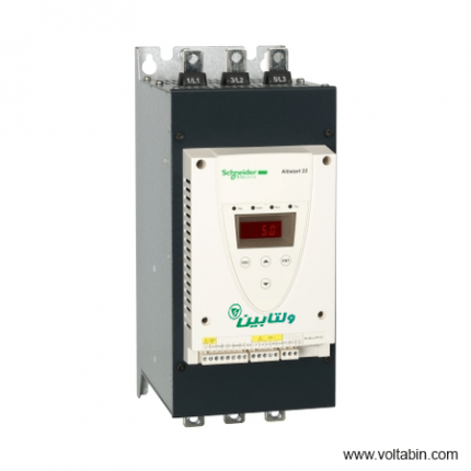
ATS22C17Q
range of product
Easy Altivar 610
product or component type
Variable speed drive
product specific application
Fan, pump, compressor, conveyor
device short name
ATV610
variant
Standard version
product destination
Asynchronous motors
mounting mode
Cabinet mount
EMC filter
Integrated conforming to EN/IEC 61800-3 category C3 with 50 m
IP degree of protection
IP20
type of cooling
Forced convection
supply frequency
50…60 Hz +/-5 %
network number of phases
3 phases
[Us] rated supply voltage
380…460 V – 15…10 %
motor power kW
110 kW for normal duty
90 kW for heavy duty
motor power hp
150 hp for normal duty
125 hp for heavy duty
line current
201 A at 380 V (normal duty)
175.7 A at 460 V (normal duty)
170 A at 380 V (heavy duty)
149.1 A at 460 V (heavy duty)
prospective line Isc
50 kA
apparent power
140.0 kVA at 460 V (normal duty)
118.8 kVA at 460 V (heavy duty)
continuous output current
211 A at 2.5 kHz for normal duty
173 A at 2.5 kHz for heavy duty
maximum transient current
232 A during 60 s (normal duty)
260 A during 60 s (heavy duty)
asynchronous motor control profile
Variable torque standard
Optimized torque mode
Constant torque standard
output frequency
0.0001…0.5 kHz
nominal switching frequency
2.5 kHz
switching frequency
1…8 kHz adjustable
number of preset speeds
16 preset speeds
communication port protocol
Modbus serial
option card
Slot A: communication card, Profibus DP V1
Slot A: digital or analog I/O extension card
Slot A: relay output card
output voltage
<= power supply voltage
motor slip compensation
Can be suppressed
Adjustable
Not available in permanent magnet motor law
Automatic whatever the load
acceleration and deceleration ramps
Linear adjustable separately from 0.01 to 9000 s
S, U or customized
braking to standstill
By DC injection
protection type
Thermal protection: motor
Motor phase break: motor
Thermal protection: drive
Overheating: drive
Overcurrent between output phases and earth: drive
Overload of output voltage: drive
Short-circuit protection: drive
Motor phase break: drive
Overvoltages on the DC bus: drive
Line supply overvoltage: drive
Line supply undervoltage: drive
Line supply phase loss: drive
Overspeed: drive
Break on the control circuit: drive
frequency resolution
Display unit: 0.1 Hz
Analog input: 0.012/50 Hz
electrical connection
Control, screw terminal: 0.5…1.5 mm²
Line side, screw terminal: 2 x 50…3 x 120 mm²
Motor, screw terminal: 3 x 50…3 x 120 mm²
connector type
1 RJ45 (on the remote graphic terminal) for Modbus serial
physical interface
2-wire RS 485 for Modbus serial
transmission frame
RTU for Modbus serial
transmission rate
4.8, 9.6, 19.2, 38.4 kbit/s for Modbus serial
type of polarization
No impedance for Modbus serial
number of addresses
1…247 for Modbus serial
method of access
Slave
supply
External supply for digital inputs: 24 V DC (19…30 V), <1.25 mA, protection type: overload and short-circuit protection
Internal supply for reference potentiometer (1 to 10 kOhm): 10.5 V DC +/- 5 %, <10 mA, protection type: overload and short-circuit protection
local signalling
2 LEDs for local diagnostic
1 LED (yellow) for embedded communication status
2 LEDs (dual colour) for communication module status
1 LED (red) for presence of voltage
width
320 mm
height
852 mm
1159 mm with IP21 conformity kit
depth
390 mm
net weight
82 kg
analogue input number
3
analogue input type
AI1, AI2, AI3 software-configurable voltage: 0…10 V DC, impedance: 30 kOhm, resolution 12 bits
AI1, AI2, AI3 software-configurable current: 0…20 mA, impedance: 250 Ohm, resolution 12 bits
AI2, AI3 software-configurable temperature probe or water level sensor
discrete input number
6
discrete input type
DI1…DI6 programmable as logic input, 24 V DC (<= 30 V), impedance: 3.5 kOhm
DI5, DI6 programmable as pulse input: 0…30 kHz, 24 V DC (<= 30 V)
input compatibility
DI1…DI6: logic input level 1 PLC conforming to EN/IEC 61131-2
DI5, DI6: pulse input level 1 PLC conforming to IEC 65A-68
discrete input logic
Positive logic (source): DI1…DI6 configurable logic input, < 5 V (state 0), > 11 V (state 1)
Negative logic (sink): DI1…DI6 configurable logic input, > 16 V (state 0), < 10 V (state 1)
Positive logic (source): DI5, DI6 configurable pulse input, < 0.6 V (state 0), > 2.5 V (state 1)
analogue output number
2
analogue output type
Software-configurable current AQ1, AQ2: 0…20 mA, resolution 10 bits
Software-configurable voltage AQ1, AQ2: 0…10 V DC impedance 470 Ohm, resolution 10 bits
sampling duration
5 ms +/- 0.1 ms (AI1, AI2, AI3) – analog input
2 ms +/- 0.5 ms (DI1…DI6)configurable – discrete input
5 ms +/- 1 ms (DI5, DI6)configurable – pulse input
10 ms +/- 1 ms (AQ1, AQ2) – analog output
accuracy
+/- 0.6 % AI1, AI2, AI3 for a temperature variation 60 °C analog input
+/- 1 % AQ1, AQ2 for a temperature variation 60 °C analog output
linearity error
AI1, AI2, AI3: +/- 0.15 % of maximum value for analog input
AQ1, AQ2: +/- 0.2 % for analog output
relay output number
3
relay output type
Configurable relay logic R1: fault relay NO/NC electrical durability 100000 cycles
Configurable relay logic R2: sequence relay NO electrical durability 100000 cycles
Configurable relay logic R3: sequence relay NO electrical durability 100000 cycles
refresh time
Relay output (R1, R2, R3): 5 ms (+/- 0.5 ms)
minimum switching current
Relay output R1, R2, R3: 5 mA at 24 V DC
maximum switching current
Relay output R1, R2, R3 on resistive load, cos phi = 1: 3 A at 250 V AC
Relay output R1, R2, R3 on resistive load, cos phi = 1: 3 A at 30 V DC
Relay output R1, R2, R3 on inductive load, cos phi = 0.4 and L/R = 7 ms: 2 A at 250 V AC
Relay output R1, R2, R3 on inductive load, cos phi = 0.4 and L/R = 7 ms: 2 A at 30 V DC
isolation
Between power and control terminals
insulation resistance
> 1 MOhm 500 V DC for 1 minute to earth
noise level
76 dB conforming to 86/188/EEC
power dissipation in W
2026 W(forced convection) at 380 V, switching frequency 2.5 kHz
operating position
Vertical +/- 10 degree
electromagnetic compatibility
Electrostatic discharge immunity test level 3 conforming to IEC 61000-4-2
Radiated radio-frequency electromagnetic field immunity test level 3 conforming to IEC 61000-4-3
Electrical fast transient/burst immunity test level 4 conforming to IEC 61000-4-4
1.2/50 µs – 8/20 µs surge immunity test level 3 conforming to IEC 61000-4-5
Conducted radio-frequency immunity test level 3 conforming to IEC 61000-4-6
pollution degree
2 conforming to EN/IEC 61800-5-1
vibration resistance
1.5 mm peak to peak (f= 2…13 Hz) conforming to IEC 60068-2-6
1 gn (f= 13…200 Hz) conforming to IEC 60068-2-6
shock resistance
6 gn for 11 ms conforming to IEC 60068-2-27
relative humidity
5…95 % without condensation conforming to IEC 60068-2-3
ambient air temperature for operation
-15…45 °C (without derating)
45…60 °C (with derating factor)
operating altitude
<= 1000 m without derating
1000…4800 m with current derating 1 % per 100 m
environmental characteristic
Chemical pollution resistance class 3C3 conforming to EN/IEC 60721-3-3
Dust pollution resistance class 3S3 conforming to EN/IEC 60721-3-3
standards
EN/IEC 61800-3
Environment 2 category C3 EN/IEC 61800-3
EN/IEC 61800-5-1
IEC 60721-3
marking
CE
Unit Type of Package 1
PCE
Number of Units in Package 1
1
Package 1 Weight
96.344 kg
Package 1 Height
47 cm
Package 1 width
67 cm
Package 1 Length
103 cm
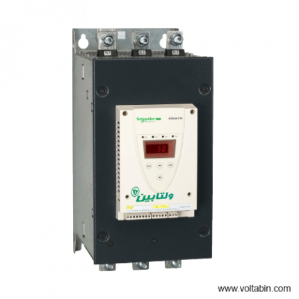
ATS22C41Q
-
range of product Easy Altivar 610 product or component type Variable speed drive product specific application Fan, pump, compressor, conveyor device short name ATV610 variant Standard version product destination Asynchronous motors mounting mode Cabinet mount EMC filter Integrated conforming to EN/IEC 61800-3 category C3 with 50 m IP degree of protection IP20 type of cooling Forced convection supply frequency 50…60 Hz +/-5 % network number of phases 3 phases [Us] rated supply voltage 380…460 V – 15…10 % motor power kW 110 kW for normal duty 90 kW for heavy duty motor power hp 150 hp for normal duty 125 hp for heavy duty line current 201 A at 380 V (normal duty) 175.7 A at 460 V (normal duty) 170 A at 380 V (heavy duty) 149.1 A at 460 V (heavy duty) prospective line Isc 50 kA apparent power 140.0 kVA at 460 V (normal duty) 118.8 kVA at 460 V (heavy duty) continuous output current 211 A at 2.5 kHz for normal duty 173 A at 2.5 kHz for heavy duty maximum transient current 232 A during 60 s (normal duty) 260 A during 60 s (heavy duty) asynchronous motor control profile Variable torque standard Optimized torque mode Constant torque standard output frequency 0.0001…0.5 kHz nominal switching frequency 2.5 kHz switching frequency 1…8 kHz adjustable number of preset speeds 16 preset speeds communication port protocol Modbus serial option card Slot A: communication card, Profibus DP V1 Slot A: digital or analog I/O extension card Slot A: relay output card output voltage <= power supply voltage motor slip compensation Can be suppressed Adjustable Not available in permanent magnet motor law Automatic whatever the load acceleration and deceleration ramps Linear adjustable separately from 0.01 to 9000 s S, U or customized braking to standstill By DC injection protection type Thermal protection: motor Motor phase break: motor Thermal protection: drive Overheating: drive Overcurrent between output phases and earth: drive Overload of output voltage: drive Short-circuit protection: drive Motor phase break: drive Overvoltages on the DC bus: drive Line supply overvoltage: drive Line supply undervoltage: drive Line supply phase loss: drive Overspeed: drive Break on the control circuit: drive frequency resolution Display unit: 0.1 Hz Analog input: 0.012/50 Hz electrical connection Control, screw terminal: 0.5…1.5 mm² Line side, screw terminal: 2 x 50…3 x 120 mm² Motor, screw terminal: 3 x 50…3 x 120 mm² connector type 1 RJ45 (on the remote graphic terminal) for Modbus serial physical interface 2-wire RS 485 for Modbus serial transmission frame RTU for Modbus serial transmission rate 4.8, 9.6, 19.2, 38.4 kbit/s for Modbus serial type of polarization No impedance for Modbus serial number of addresses 1…247 for Modbus serial method of access Slave supply External supply for digital inputs: 24 V DC (19…30 V), <1.25 mA, protection type: overload and short-circuit protection Internal supply for reference potentiometer (1 to 10 kOhm): 10.5 V DC +/- 5 %, <10 mA, protection type: overload and short-circuit protection local signalling 2 LEDs for local diagnostic 1 LED (yellow) for embedded communication status 2 LEDs (dual colour) for communication module status 1 LED (red) for presence of voltage width 320 mm height 852 mm 1159 mm with IP21 conformity kit depth 390 mm net weight 82 kg analogue input number 3 analogue input type AI1, AI2, AI3 software-configurable voltage: 0…10 V DC, impedance: 30 kOhm, resolution 12 bits AI1, AI2, AI3 software-configurable current: 0…20 mA, impedance: 250 Ohm, resolution 12 bits AI2, AI3 software-configurable temperature probe or water level sensor discrete input number 6 discrete input type DI1…DI6 programmable as logic input, 24 V DC (<= 30 V), impedance: 3.5 kOhm DI5, DI6 programmable as pulse input: 0…30 kHz, 24 V DC (<= 30 V) input compatibility DI1…DI6: logic input level 1 PLC conforming to EN/IEC 61131-2 DI5, DI6: pulse input level 1 PLC conforming to IEC 65A-68 discrete input logic Positive logic (source): DI1…DI6 configurable logic input, < 5 V (state 0), > 11 V (state 1) Negative logic (sink): DI1…DI6 configurable logic input, > 16 V (state 0), < 10 V (state 1) Positive logic (source): DI5, DI6 configurable pulse input, < 0.6 V (state 0), > 2.5 V (state 1) analogue output number 2 analogue output type Software-configurable current AQ1, AQ2: 0…20 mA, resolution 10 bits Software-configurable voltage AQ1, AQ2: 0…10 V DC impedance 470 Ohm, resolution 10 bits sampling duration 5 ms +/- 0.1 ms (AI1, AI2, AI3) – analog input 2 ms +/- 0.5 ms (DI1…DI6)configurable – discrete input 5 ms +/- 1 ms (DI5, DI6)configurable – pulse input 10 ms +/- 1 ms (AQ1, AQ2) – analog output accuracy +/- 0.6 % AI1, AI2, AI3 for a temperature variation 60 °C analog input +/- 1 % AQ1, AQ2 for a temperature variation 60 °C analog output linearity error AI1, AI2, AI3: +/- 0.15 % of maximum value for analog input AQ1, AQ2: +/- 0.2 % for analog output relay output number 3 relay output type Configurable relay logic R1: fault relay NO/NC electrical durability 100000 cycles Configurable relay logic R2: sequence relay NO electrical durability 100000 cycles Configurable relay logic R3: sequence relay NO electrical durability 100000 cycles refresh time Relay output (R1, R2, R3): 5 ms (+/- 0.5 ms) minimum switching current Relay output R1, R2, R3: 5 mA at 24 V DC maximum switching current Relay output R1, R2, R3 on resistive load, cos phi = 1: 3 A at 250 V AC Relay output R1, R2, R3 on resistive load, cos phi = 1: 3 A at 30 V DC Relay output R1, R2, R3 on inductive load, cos phi = 0.4 and L/R = 7 ms: 2 A at 250 V AC Relay output R1, R2, R3 on inductive load, cos phi = 0.4 and L/R = 7 ms: 2 A at 30 V DC isolation Between power and control terminals insulation resistance > 1 MOhm 500 V DC for 1 minute to earth noise level 76 dB conforming to 86/188/EEC power dissipation in W 2026 W(forced convection) at 380 V, switching frequency 2.5 kHz operating position Vertical +/- 10 degree electromagnetic compatibility Electrostatic discharge immunity test level 3 conforming to IEC 61000-4-2 Radiated radio-frequency electromagnetic field immunity test level 3 conforming to IEC 61000-4-3 Electrical fast transient/burst immunity test level 4 conforming to IEC 61000-4-4 1.2/50 µs – 8/20 µs surge immunity test level 3 conforming to IEC 61000-4-5 Conducted radio-frequency immunity test level 3 conforming to IEC 61000-4-6 pollution degree 2 conforming to EN/IEC 61800-5-1 vibration resistance 1.5 mm peak to peak (f= 2…13 Hz) conforming to IEC 60068-2-6 1 gn (f= 13…200 Hz) conforming to IEC 60068-2-6 shock resistance 6 gn for 11 ms conforming to IEC 60068-2-27 relative humidity 5…95 % without condensation conforming to IEC 60068-2-3 ambient air temperature for operation -15…45 °C (without derating) 45…60 °C (with derating factor) operating altitude <= 1000 m without derating 1000…4800 m with current derating 1 % per 100 m environmental characteristic Chemical pollution resistance class 3C3 conforming to EN/IEC 60721-3-3 Dust pollution resistance class 3S3 conforming to EN/IEC 60721-3-3 standards EN/IEC 61800-3 Environment 2 category C3 EN/IEC 61800-3 EN/IEC 61800-5-1 IEC 60721-3 marking CE Unit Type of Package 1 PCE Number of Units in Package 1 1 Package 1 Weight 96.344 kg Package 1 Height 47 cm Package 1 width 67 cm Package 1 Length 103 cm
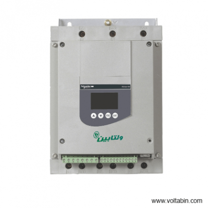
ATS48D62Q
-
range of product Easy Altivar 610 product or component type Variable speed drive product specific application Fan, pump, compressor, conveyor device short name ATV610 variant Standard version product destination Asynchronous motors mounting mode Cabinet mount EMC filter Integrated conforming to EN/IEC 61800-3 category C3 with 50 m IP degree of protection IP20 type of cooling Forced convection supply frequency 50…60 Hz +/-5 % network number of phases 3 phases [Us] rated supply voltage 380…460 V – 15…10 % motor power kW 110 kW for normal duty 90 kW for heavy duty motor power hp 150 hp for normal duty 125 hp for heavy duty line current 201 A at 380 V (normal duty) 175.7 A at 460 V (normal duty) 170 A at 380 V (heavy duty) 149.1 A at 460 V (heavy duty) prospective line Isc 50 kA apparent power 140.0 kVA at 460 V (normal duty) 118.8 kVA at 460 V (heavy duty) continuous output current 211 A at 2.5 kHz for normal duty 173 A at 2.5 kHz for heavy duty maximum transient current 232 A during 60 s (normal duty) 260 A during 60 s (heavy duty) asynchronous motor control profile Variable torque standard Optimized torque mode Constant torque standard output frequency 0.0001…0.5 kHz nominal switching frequency 2.5 kHz switching frequency 1…8 kHz adjustable number of preset speeds 16 preset speeds communication port protocol Modbus serial option card Slot A: communication card, Profibus DP V1 Slot A: digital or analog I/O extension card Slot A: relay output card output voltage <= power supply voltage motor slip compensation Can be suppressed Adjustable Not available in permanent magnet motor law Automatic whatever the load acceleration and deceleration ramps Linear adjustable separately from 0.01 to 9000 s S, U or customized braking to standstill By DC injection protection type Thermal protection: motor Motor phase break: motor Thermal protection: drive Overheating: drive Overcurrent between output phases and earth: drive Overload of output voltage: drive Short-circuit protection: drive Motor phase break: drive Overvoltages on the DC bus: drive Line supply overvoltage: drive Line supply undervoltage: drive Line supply phase loss: drive Overspeed: drive Break on the control circuit: drive frequency resolution Display unit: 0.1 Hz Analog input: 0.012/50 Hz electrical connection Control, screw terminal: 0.5…1.5 mm² Line side, screw terminal: 2 x 50…3 x 120 mm² Motor, screw terminal: 3 x 50…3 x 120 mm² connector type 1 RJ45 (on the remote graphic terminal) for Modbus serial physical interface 2-wire RS 485 for Modbus serial transmission frame RTU for Modbus serial transmission rate 4.8, 9.6, 19.2, 38.4 kbit/s for Modbus serial type of polarization No impedance for Modbus serial number of addresses 1…247 for Modbus serial method of access Slave supply External supply for digital inputs: 24 V DC (19…30 V), <1.25 mA, protection type: overload and short-circuit protection Internal supply for reference potentiometer (1 to 10 kOhm): 10.5 V DC +/- 5 %, <10 mA, protection type: overload and short-circuit protection local signalling 2 LEDs for local diagnostic 1 LED (yellow) for embedded communication status 2 LEDs (dual colour) for communication module status 1 LED (red) for presence of voltage width 320 mm height 852 mm 1159 mm with IP21 conformity kit depth 390 mm net weight 82 kg analogue input number 3 analogue input type AI1, AI2, AI3 software-configurable voltage: 0…10 V DC, impedance: 30 kOhm, resolution 12 bits AI1, AI2, AI3 software-configurable current: 0…20 mA, impedance: 250 Ohm, resolution 12 bits AI2, AI3 software-configurable temperature probe or water level sensor discrete input number 6 discrete input type DI1…DI6 programmable as logic input, 24 V DC (<= 30 V), impedance: 3.5 kOhm DI5, DI6 programmable as pulse input: 0…30 kHz, 24 V DC (<= 30 V) input compatibility DI1…DI6: logic input level 1 PLC conforming to EN/IEC 61131-2 DI5, DI6: pulse input level 1 PLC conforming to IEC 65A-68 discrete input logic Positive logic (source): DI1…DI6 configurable logic input, < 5 V (state 0), > 11 V (state 1) Negative logic (sink): DI1…DI6 configurable logic input, > 16 V (state 0), < 10 V (state 1) Positive logic (source): DI5, DI6 configurable pulse input, < 0.6 V (state 0), > 2.5 V (state 1) analogue output number 2 analogue output type Software-configurable current AQ1, AQ2: 0…20 mA, resolution 10 bits Software-configurable voltage AQ1, AQ2: 0…10 V DC impedance 470 Ohm, resolution 10 bits sampling duration 5 ms +/- 0.1 ms (AI1, AI2, AI3) – analog input 2 ms +/- 0.5 ms (DI1…DI6)configurable – discrete input 5 ms +/- 1 ms (DI5, DI6)configurable – pulse input 10 ms +/- 1 ms (AQ1, AQ2) – analog output accuracy +/- 0.6 % AI1, AI2, AI3 for a temperature variation 60 °C analog input +/- 1 % AQ1, AQ2 for a temperature variation 60 °C analog output linearity error AI1, AI2, AI3: +/- 0.15 % of maximum value for analog input AQ1, AQ2: +/- 0.2 % for analog output relay output number 3 relay output type Configurable relay logic R1: fault relay NO/NC electrical durability 100000 cycles Configurable relay logic R2: sequence relay NO electrical durability 100000 cycles Configurable relay logic R3: sequence relay NO electrical durability 100000 cycles refresh time Relay output (R1, R2, R3): 5 ms (+/- 0.5 ms) minimum switching current Relay output R1, R2, R3: 5 mA at 24 V DC maximum switching current Relay output R1, R2, R3 on resistive load, cos phi = 1: 3 A at 250 V AC Relay output R1, R2, R3 on resistive load, cos phi = 1: 3 A at 30 V DC Relay output R1, R2, R3 on inductive load, cos phi = 0.4 and L/R = 7 ms: 2 A at 250 V AC Relay output R1, R2, R3 on inductive load, cos phi = 0.4 and L/R = 7 ms: 2 A at 30 V DC isolation Between power and control terminals insulation resistance > 1 MOhm 500 V DC for 1 minute to earth noise level 76 dB conforming to 86/188/EEC power dissipation in W 2026 W(forced convection) at 380 V, switching frequency 2.5 kHz operating position Vertical +/- 10 degree electromagnetic compatibility Electrostatic discharge immunity test level 3 conforming to IEC 61000-4-2 Radiated radio-frequency electromagnetic field immunity test level 3 conforming to IEC 61000-4-3 Electrical fast transient/burst immunity test level 4 conforming to IEC 61000-4-4 1.2/50 µs – 8/20 µs surge immunity test level 3 conforming to IEC 61000-4-5 Conducted radio-frequency immunity test level 3 conforming to IEC 61000-4-6 pollution degree 2 conforming to EN/IEC 61800-5-1 vibration resistance 1.5 mm peak to peak (f= 2…13 Hz) conforming to IEC 60068-2-6 1 gn (f= 13…200 Hz) conforming to IEC 60068-2-6 shock resistance 6 gn for 11 ms conforming to IEC 60068-2-27 relative humidity 5…95 % without condensation conforming to IEC 60068-2-3 ambient air temperature for operation -15…45 °C (without derating) 45…60 °C (with derating factor) operating altitude <= 1000 m without derating 1000…4800 m with current derating 1 % per 100 m environmental characteristic Chemical pollution resistance class 3C3 conforming to EN/IEC 60721-3-3 Dust pollution resistance class 3S3 conforming to EN/IEC 60721-3-3 standards EN/IEC 61800-3 Environment 2 category C3 EN/IEC 61800-3 EN/IEC 61800-5-1 IEC 60721-3 marking CE Unit Type of Package 1 PCE Number of Units in Package 1 1 Package 1 Weight 96.344 kg Package 1 Height 47 cm Package 1 width 67 cm Package 1 Length 103 cm
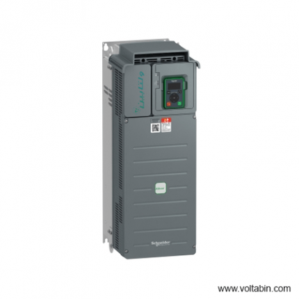
ATV610D30N4
range of product
Easy Altivar 610
product or component type
Variable speed drive
product specific application
Fan, pump, compressor, conveyor
device short name
ATV610
variant
Standard version
product destination
Asynchronous motors
mounting mode
Cabinet mount
EMC filter
Integrated conforming to EN/IEC 61800-3 category C3 with 50 m
IP degree of protection
IP20
type of cooling
Forced convection
supply frequency
50…60 Hz +/-5 %
network number of phases
3 phases
[Us] rated supply voltage
380…460 V – 15…10 %
motor power kW
110 kW for normal duty
90 kW for heavy duty
motor power hp
150 hp for normal duty
125 hp for heavy duty
line current
201 A at 380 V (normal duty)
175.7 A at 460 V (normal duty)
170 A at 380 V (heavy duty)
149.1 A at 460 V (heavy duty)
prospective line Isc
50 kA
apparent power
140.0 kVA at 460 V (normal duty)
118.8 kVA at 460 V (heavy duty)
continuous output current
211 A at 2.5 kHz for normal duty
173 A at 2.5 kHz for heavy duty
maximum transient current
232 A during 60 s (normal duty)
260 A during 60 s (heavy duty)
asynchronous motor control profile
Variable torque standard
Optimized torque mode
Constant torque standard
output frequency
0.0001…0.5 kHz
nominal switching frequency
2.5 kHz
switching frequency
1…8 kHz adjustable
number of preset speeds
16 preset speeds
communication port protocol
Modbus serial
option card
Slot A: communication card, Profibus DP V1
Slot A: digital or analog I/O extension card
Slot A: relay output card
output voltage
<= power supply voltage
motor slip compensation
Can be suppressed
Adjustable
Not available in permanent magnet motor law
Automatic whatever the load
acceleration and deceleration ramps
Linear adjustable separately from 0.01 to 9000 s
S, U or customized
braking to standstill
By DC injection
protection type
Thermal protection: motor
Motor phase break: motor
Thermal protection: drive
Overheating: drive
Overcurrent between output phases and earth: drive
Overload of output voltage: drive
Short-circuit protection: drive
Motor phase break: drive
Overvoltages on the DC bus: drive
Line supply overvoltage: drive
Line supply undervoltage: drive
Line supply phase loss: drive
Overspeed: drive
Break on the control circuit: drive
frequency resolution
Display unit: 0.1 Hz
Analog input: 0.012/50 Hz
electrical connection
Control, screw terminal: 0.5…1.5 mm²
Line side, screw terminal: 2 x 50…3 x 120 mm²
Motor, screw terminal: 3 x 50…3 x 120 mm²
connector type
1 RJ45 (on the remote graphic terminal) for Modbus serial
physical interface
2-wire RS 485 for Modbus serial
transmission frame
RTU for Modbus serial
transmission rate
4.8, 9.6, 19.2, 38.4 kbit/s for Modbus serial
type of polarization
No impedance for Modbus serial
number of addresses
1…247 for Modbus serial
method of access
Slave
supply
External supply for digital inputs: 24 V DC (19…30 V), <1.25 mA, protection type: overload and short-circuit protection
Internal supply for reference potentiometer (1 to 10 kOhm): 10.5 V DC +/- 5 %, <10 mA, protection type: overload and short-circuit protection
local signalling
2 LEDs for local diagnostic
1 LED (yellow) for embedded communication status
2 LEDs (dual colour) for communication module status
1 LED (red) for presence of voltage
width
320 mm
height
852 mm
1159 mm with IP21 conformity kit
depth
390 mm
net weight
82 kg
analogue input number
3
analogue input type
AI1, AI2, AI3 software-configurable voltage: 0…10 V DC, impedance: 30 kOhm, resolution 12 bits
AI1, AI2, AI3 software-configurable current: 0…20 mA, impedance: 250 Ohm, resolution 12 bits
AI2, AI3 software-configurable temperature probe or water level sensor
discrete input number
6
discrete input type
DI1…DI6 programmable as logic input, 24 V DC (<= 30 V), impedance: 3.5 kOhm
DI5, DI6 programmable as pulse input: 0…30 kHz, 24 V DC (<= 30 V)
input compatibility
DI1…DI6: logic input level 1 PLC conforming to EN/IEC 61131-2
DI5, DI6: pulse input level 1 PLC conforming to IEC 65A-68
discrete input logic
Positive logic (source): DI1…DI6 configurable logic input, < 5 V (state 0), > 11 V (state 1)
Negative logic (sink): DI1…DI6 configurable logic input, > 16 V (state 0), < 10 V (state 1)
Positive logic (source): DI5, DI6 configurable pulse input, < 0.6 V (state 0), > 2.5 V (state 1)
analogue output number
2
analogue output type
Software-configurable current AQ1, AQ2: 0…20 mA, resolution 10 bits
Software-configurable voltage AQ1, AQ2: 0…10 V DC impedance 470 Ohm, resolution 10 bits
sampling duration
5 ms +/- 0.1 ms (AI1, AI2, AI3) – analog input
2 ms +/- 0.5 ms (DI1…DI6)configurable – discrete input
5 ms +/- 1 ms (DI5, DI6)configurable – pulse input
10 ms +/- 1 ms (AQ1, AQ2) – analog output
accuracy
+/- 0.6 % AI1, AI2, AI3 for a temperature variation 60 °C analog input
+/- 1 % AQ1, AQ2 for a temperature variation 60 °C analog output
linearity error
AI1, AI2, AI3: +/- 0.15 % of maximum value for analog input
AQ1, AQ2: +/- 0.2 % for analog output
relay output number
3
relay output type
Configurable relay logic R1: fault relay NO/NC electrical durability 100000 cycles
Configurable relay logic R2: sequence relay NO electrical durability 100000 cycles
Configurable relay logic R3: sequence relay NO electrical durability 100000 cycles
refresh time
Relay output (R1, R2, R3): 5 ms (+/- 0.5 ms)
minimum switching current
Relay output R1, R2, R3: 5 mA at 24 V DC
maximum switching current
Relay output R1, R2, R3 on resistive load, cos phi = 1: 3 A at 250 V AC
Relay output R1, R2, R3 on resistive load, cos phi = 1: 3 A at 30 V DC
Relay output R1, R2, R3 on inductive load, cos phi = 0.4 and L/R = 7 ms: 2 A at 250 V AC
Relay output R1, R2, R3 on inductive load, cos phi = 0.4 and L/R = 7 ms: 2 A at 30 V DC
isolation
Between power and control terminals
insulation resistance
> 1 MOhm 500 V DC for 1 minute to earth
noise level
76 dB conforming to 86/188/EEC
power dissipation in W
2026 W(forced convection) at 380 V, switching frequency 2.5 kHz
operating position
Vertical +/- 10 degree
electromagnetic compatibility
Electrostatic discharge immunity test level 3 conforming to IEC 61000-4-2
Radiated radio-frequency electromagnetic field immunity test level 3 conforming to IEC 61000-4-3
Electrical fast transient/burst immunity test level 4 conforming to IEC 61000-4-4
1.2/50 µs – 8/20 µs surge immunity test level 3 conforming to IEC 61000-4-5
Conducted radio-frequency immunity test level 3 conforming to IEC 61000-4-6
pollution degree
2 conforming to EN/IEC 61800-5-1
vibration resistance
1.5 mm peak to peak (f= 2…13 Hz) conforming to IEC 60068-2-6
1 gn (f= 13…200 Hz) conforming to IEC 60068-2-6
shock resistance
6 gn for 11 ms conforming to IEC 60068-2-27
relative humidity
5…95 % without condensation conforming to IEC 60068-2-3
ambient air temperature for operation
-15…45 °C (without derating)
45…60 °C (with derating factor)
operating altitude
<= 1000 m without derating
1000…4800 m with current derating 1 % per 100 m
environmental characteristic
Chemical pollution resistance class 3C3 conforming to EN/IEC 60721-3-3
Dust pollution resistance class 3S3 conforming to EN/IEC 60721-3-3
standards
EN/IEC 61800-3
Environment 2 category C3 EN/IEC 61800-3
EN/IEC 61800-5-1
IEC 60721-3
marking
CE
Unit Type of Package 1
PCE
Number of Units in Package 1
1
Package 1 Weight
96.344 kg
Package 1 Height
47 cm
Package 1 width
67 cm
Package 1 Length
103 cm
ATV630D22N4
range of product
Easy Altivar 610
product or component type
Variable speed drive
product specific application
Fan, pump, compressor, conveyor
device short name
ATV610
variant
Standard version
product destination
Asynchronous motors
mounting mode
Cabinet mount
EMC filter
Integrated conforming to EN/IEC 61800-3 category C3 with 50 m
IP degree of protection
IP20
type of cooling
Forced convection
supply frequency
50…60 Hz +/-5 %
network number of phases
3 phases
[Us] rated supply voltage
380…460 V – 15…10 %
motor power kW
110 kW for normal duty
90 kW for heavy duty
motor power hp
150 hp for normal duty
125 hp for heavy duty
line current
201 A at 380 V (normal duty)
175.7 A at 460 V (normal duty)
170 A at 380 V (heavy duty)
149.1 A at 460 V (heavy duty)
prospective line Isc
50 kA
apparent power
140.0 kVA at 460 V (normal duty)
118.8 kVA at 460 V (heavy duty)
continuous output current
211 A at 2.5 kHz for normal duty
173 A at 2.5 kHz for heavy duty
maximum transient current
232 A during 60 s (normal duty)
260 A during 60 s (heavy duty)
asynchronous motor control profile
Variable torque standard
Optimized torque mode
Constant torque standard
output frequency
0.0001…0.5 kHz
nominal switching frequency
2.5 kHz
switching frequency
1…8 kHz adjustable
number of preset speeds
16 preset speeds
communication port protocol
Modbus serial
option card
Slot A: communication card, Profibus DP V1
Slot A: digital or analog I/O extension card
Slot A: relay output card
output voltage
<= power supply voltage
motor slip compensation
Can be suppressed
Adjustable
Not available in permanent magnet motor law
Automatic whatever the load
acceleration and deceleration ramps
Linear adjustable separately from 0.01 to 9000 s
S, U or customized
braking to standstill
By DC injection
protection type
Thermal protection: motor
Motor phase break: motor
Thermal protection: drive
Overheating: drive
Overcurrent between output phases and earth: drive
Overload of output voltage: drive
Short-circuit protection: drive
Motor phase break: drive
Overvoltages on the DC bus: drive
Line supply overvoltage: drive
Line supply undervoltage: drive
Line supply phase loss: drive
Overspeed: drive
Break on the control circuit: drive
frequency resolution
Display unit: 0.1 Hz
Analog input: 0.012/50 Hz
electrical connection
Control, screw terminal: 0.5…1.5 mm²
Line side, screw terminal: 2 x 50…3 x 120 mm²
Motor, screw terminal: 3 x 50…3 x 120 mm²
connector type
1 RJ45 (on the remote graphic terminal) for Modbus serial
physical interface
2-wire RS 485 for Modbus serial
transmission frame
RTU for Modbus serial
transmission rate
4.8, 9.6, 19.2, 38.4 kbit/s for Modbus serial
type of polarization
No impedance for Modbus serial
number of addresses
1…247 for Modbus serial
method of access
Slave
supply
External supply for digital inputs: 24 V DC (19…30 V), <1.25 mA, protection type: overload and short-circuit protection
Internal supply for reference potentiometer (1 to 10 kOhm): 10.5 V DC +/- 5 %, <10 mA, protection type: overload and short-circuit protection
local signalling
2 LEDs for local diagnostic
1 LED (yellow) for embedded communication status
2 LEDs (dual colour) for communication module status
1 LED (red) for presence of voltage
width
320 mm
height
852 mm
1159 mm with IP21 conformity kit
depth
390 mm
net weight
82 kg
analogue input number
3
analogue input type
AI1, AI2, AI3 software-configurable voltage: 0…10 V DC, impedance: 30 kOhm, resolution 12 bits
AI1, AI2, AI3 software-configurable current: 0…20 mA, impedance: 250 Ohm, resolution 12 bits
AI2, AI3 software-configurable temperature probe or water level sensor
discrete input number
6
discrete input type
DI1…DI6 programmable as logic input, 24 V DC (<= 30 V), impedance: 3.5 kOhm
DI5, DI6 programmable as pulse input: 0…30 kHz, 24 V DC (<= 30 V)
input compatibility
DI1…DI6: logic input level 1 PLC conforming to EN/IEC 61131-2
DI5, DI6: pulse input level 1 PLC conforming to IEC 65A-68
discrete input logic
Positive logic (source): DI1…DI6 configurable logic input, < 5 V (state 0), > 11 V (state 1)
Negative logic (sink): DI1…DI6 configurable logic input, > 16 V (state 0), < 10 V (state 1)
Positive logic (source): DI5, DI6 configurable pulse input, < 0.6 V (state 0), > 2.5 V (state 1)
analogue output number
2
analogue output type
Software-configurable current AQ1, AQ2: 0…20 mA, resolution 10 bits
Software-configurable voltage AQ1, AQ2: 0…10 V DC impedance 470 Ohm, resolution 10 bits
sampling duration
5 ms +/- 0.1 ms (AI1, AI2, AI3) – analog input
2 ms +/- 0.5 ms (DI1…DI6)configurable – discrete input
5 ms +/- 1 ms (DI5, DI6)configurable – pulse input
10 ms +/- 1 ms (AQ1, AQ2) – analog output
accuracy
+/- 0.6 % AI1, AI2, AI3 for a temperature variation 60 °C analog input
+/- 1 % AQ1, AQ2 for a temperature variation 60 °C analog output
linearity error
AI1, AI2, AI3: +/- 0.15 % of maximum value for analog input
AQ1, AQ2: +/- 0.2 % for analog output
relay output number
3
relay output type
Configurable relay logic R1: fault relay NO/NC electrical durability 100000 cycles
Configurable relay logic R2: sequence relay NO electrical durability 100000 cycles
Configurable relay logic R3: sequence relay NO electrical durability 100000 cycles
refresh time
Relay output (R1, R2, R3): 5 ms (+/- 0.5 ms)
minimum switching current
Relay output R1, R2, R3: 5 mA at 24 V DC
maximum switching current
Relay output R1, R2, R3 on resistive load, cos phi = 1: 3 A at 250 V AC
Relay output R1, R2, R3 on resistive load, cos phi = 1: 3 A at 30 V DC
Relay output R1, R2, R3 on inductive load, cos phi = 0.4 and L/R = 7 ms: 2 A at 250 V AC
Relay output R1, R2, R3 on inductive load, cos phi = 0.4 and L/R = 7 ms: 2 A at 30 V DC
isolation
Between power and control terminals
insulation resistance
> 1 MOhm 500 V DC for 1 minute to earth
noise level
76 dB conforming to 86/188/EEC
power dissipation in W
2026 W(forced convection) at 380 V, switching frequency 2.5 kHz
operating position
Vertical +/- 10 degree
electromagnetic compatibility
Electrostatic discharge immunity test level 3 conforming to IEC 61000-4-2
Radiated radio-frequency electromagnetic field immunity test level 3 conforming to IEC 61000-4-3
Electrical fast transient/burst immunity test level 4 conforming to IEC 61000-4-4
1.2/50 µs – 8/20 µs surge immunity test level 3 conforming to IEC 61000-4-5
Conducted radio-frequency immunity test level 3 conforming to IEC 61000-4-6
pollution degree
2 conforming to EN/IEC 61800-5-1
vibration resistance
1.5 mm peak to peak (f= 2…13 Hz) conforming to IEC 60068-2-6
1 gn (f= 13…200 Hz) conforming to IEC 60068-2-6
shock resistance
6 gn for 11 ms conforming to IEC 60068-2-27
relative humidity
5…95 % without condensation conforming to IEC 60068-2-3
ambient air temperature for operation
-15…45 °C (without derating)
45…60 °C (with derating factor)
operating altitude
<= 1000 m without derating
1000…4800 m with current derating 1 % per 100 m
environmental characteristic
Chemical pollution resistance class 3C3 conforming to EN/IEC 60721-3-3
Dust pollution resistance class 3S3 conforming to EN/IEC 60721-3-3
standards
EN/IEC 61800-3
Environment 2 category C3 EN/IEC 61800-3
EN/IEC 61800-5-1
IEC 60721-3
marking
CE
Unit Type of Package 1
PCE
Number of Units in Package 1
1
Package 1 Weight
96.344 kg
Package 1 Height
47 cm
Package 1 width
67 cm
Package 1 Length
103 cm
ATV630U15N4
| range of product | Easy Altivar 610 |
|---|---|
| product or component type | Variable speed drive |
| product specific application | Fan, pump, compressor, conveyor |
| device short name | ATV610 |
| variant | Standard version |
| product destination | Asynchronous motors |
| mounting mode | Cabinet mount |
| EMC filter | Integrated conforming to EN/IEC 61800-3 category C3 with 50 m |
| IP degree of protection | IP20 |
| type of cooling | Forced convection |
| supply frequency | 50…60 Hz +/-5 % |
| network number of phases | 3 phases |
| [Us] rated supply voltage | 380…460 V – 15…10 % |
| motor power kW | 110 kW for normal duty 90 kW for heavy duty |
| motor power hp | 150 hp for normal duty 125 hp for heavy duty |
| line current | 201 A at 380 V (normal duty) 175.7 A at 460 V (normal duty) 170 A at 380 V (heavy duty) 149.1 A at 460 V (heavy duty) |
| prospective line Isc | 50 kA |
| apparent power | 140.0 kVA at 460 V (normal duty) 118.8 kVA at 460 V (heavy duty) |
| continuous output current | 211 A at 2.5 kHz for normal duty 173 A at 2.5 kHz for heavy duty |
| maximum transient current | 232 A during 60 s (normal duty) 260 A during 60 s (heavy duty) |
| asynchronous motor control profile | Variable torque standard Optimized torque mode Constant torque standard |
| output frequency | 0.0001…0.5 kHz |
| nominal switching frequency | 2.5 kHz |
| switching frequency | 1…8 kHz adjustable |
| number of preset speeds | 16 preset speeds |
| communication port protocol | Modbus serial |
| option card | Slot A: communication card, Profibus DP V1 Slot A: digital or analog I/O extension card Slot A: relay output card |
| output voltage | <= power supply voltage |
|---|---|
| motor slip compensation | Can be suppressed Adjustable Not available in permanent magnet motor law Automatic whatever the load |
| acceleration and deceleration ramps | Linear adjustable separately from 0.01 to 9000 s S, U or customized |
| braking to standstill | By DC injection |
| protection type | Thermal protection: motor Motor phase break: motor Thermal protection: drive Overheating: drive Overcurrent between output phases and earth: drive Overload of output voltage: drive Short-circuit protection: drive Motor phase break: drive Overvoltages on the DC bus: drive Line supply overvoltage: drive Line supply undervoltage: drive Line supply phase loss: drive Overspeed: drive Break on the control circuit: drive |
| frequency resolution | Display unit: 0.1 Hz Analog input: 0.012/50 Hz |
| electrical connection | Control, screw terminal: 0.5…1.5 mm² Line side, screw terminal: 2 x 50…3 x 120 mm² Motor, screw terminal: 3 x 50…3 x 120 mm² |
| connector type | 1 RJ45 (on the remote graphic terminal) for Modbus serial |
| physical interface | 2-wire RS 485 for Modbus serial |
| transmission frame | RTU for Modbus serial |
| transmission rate | 4.8, 9.6, 19.2, 38.4 kbit/s for Modbus serial |
| type of polarization | No impedance for Modbus serial |
| number of addresses | 1…247 for Modbus serial |
| method of access | Slave |
| supply | External supply for digital inputs: 24 V DC (19…30 V), <1.25 mA, protection type: overload and short-circuit protection Internal supply for reference potentiometer (1 to 10 kOhm): 10.5 V DC +/- 5 %, <10 mA, protection type: overload and short-circuit protection |
| local signalling | 2 LEDs for local diagnostic 1 LED (yellow) for embedded communication status 2 LEDs (dual colour) for communication module status 1 LED (red) for presence of voltage |
| width | 320 mm |
| height | 852 mm 1159 mm with IP21 conformity kit |
| depth | 390 mm |
| net weight | 82 kg |
| analogue input number | 3 |
| analogue input type | AI1, AI2, AI3 software-configurable voltage: 0…10 V DC, impedance: 30 kOhm, resolution 12 bits AI1, AI2, AI3 software-configurable current: 0…20 mA, impedance: 250 Ohm, resolution 12 bits AI2, AI3 software-configurable temperature probe or water level sensor |
| discrete input number | 6 |
| discrete input type | DI1…DI6 programmable as logic input, 24 V DC (<= 30 V), impedance: 3.5 kOhm DI5, DI6 programmable as pulse input: 0…30 kHz, 24 V DC (<= 30 V) |
| input compatibility | DI1…DI6: logic input level 1 PLC conforming to EN/IEC 61131-2 DI5, DI6: pulse input level 1 PLC conforming to IEC 65A-68 |
| discrete input logic | Positive logic (source): DI1…DI6 configurable logic input, < 5 V (state 0), > 11 V (state 1) Negative logic (sink): DI1…DI6 configurable logic input, > 16 V (state 0), < 10 V (state 1) Positive logic (source): DI5, DI6 configurable pulse input, < 0.6 V (state 0), > 2.5 V (state 1) |
| analogue output number | 2 |
| analogue output type | Software-configurable current AQ1, AQ2: 0…20 mA, resolution 10 bits Software-configurable voltage AQ1, AQ2: 0…10 V DC impedance 470 Ohm, resolution 10 bits |
| sampling duration | 5 ms +/- 0.1 ms (AI1, AI2, AI3) – analog input 2 ms +/- 0.5 ms (DI1…DI6)configurable – discrete input 5 ms +/- 1 ms (DI5, DI6)configurable – pulse input 10 ms +/- 1 ms (AQ1, AQ2) – analog output |
| accuracy | +/- 0.6 % AI1, AI2, AI3 for a temperature variation 60 °C analog input +/- 1 % AQ1, AQ2 for a temperature variation 60 °C analog output |
| linearity error | AI1, AI2, AI3: +/- 0.15 % of maximum value for analog input AQ1, AQ2: +/- 0.2 % for analog output |
| relay output number | 3 |
| relay output type | Configurable relay logic R1: fault relay NO/NC electrical durability 100000 cycles Configurable relay logic R2: sequence relay NO electrical durability 100000 cycles Configurable relay logic R3: sequence relay NO electrical durability 100000 cycles |
| refresh time | Relay output (R1, R2, R3): 5 ms (+/- 0.5 ms) |
| minimum switching current | Relay output R1, R2, R3: 5 mA at 24 V DC |
| maximum switching current | Relay output R1, R2, R3 on resistive load, cos phi = 1: 3 A at 250 V AC Relay output R1, R2, R3 on resistive load, cos phi = 1: 3 A at 30 V DC Relay output R1, R2, R3 on inductive load, cos phi = 0.4 and L/R = 7 ms: 2 A at 250 V AC Relay output R1, R2, R3 on inductive load, cos phi = 0.4 and L/R = 7 ms: 2 A at 30 V DC |
| isolation | Between power and control terminals |
| insulation resistance | > 1 MOhm 500 V DC for 1 minute to earth |
| noise level | 76 dB conforming to 86/188/EEC |
|---|---|
| power dissipation in W | 2026 W(forced convection) at 380 V, switching frequency 2.5 kHz |
| operating position | Vertical +/- 10 degree |
| electromagnetic compatibility | Electrostatic discharge immunity test level 3 conforming to IEC 61000-4-2 Radiated radio-frequency electromagnetic field immunity test level 3 conforming to IEC 61000-4-3 Electrical fast transient/burst immunity test level 4 conforming to IEC 61000-4-4 1.2/50 µs – 8/20 µs surge immunity test level 3 conforming to IEC 61000-4-5 Conducted radio-frequency immunity test level 3 conforming to IEC 61000-4-6 |
| pollution degree | 2 conforming to EN/IEC 61800-5-1 |
| vibration resistance | 1.5 mm peak to peak (f= 2…13 Hz) conforming to IEC 60068-2-6 1 gn (f= 13…200 Hz) conforming to IEC 60068-2-6 |
| shock resistance | 6 gn for 11 ms conforming to IEC 60068-2-27 |
| relative humidity | 5…95 % without condensation conforming to IEC 60068-2-3 |
| ambient air temperature for operation | -15…45 °C (without derating) 45…60 °C (with derating factor) |
| operating altitude | <= 1000 m without derating 1000…4800 m with current derating 1 % per 100 m |
| environmental characteristic | Chemical pollution resistance class 3C3 conforming to EN/IEC 60721-3-3 Dust pollution resistance class 3S3 conforming to EN/IEC 60721-3-3 |
| standards | EN/IEC 61800-3 Environment 2 category C3 EN/IEC 61800-3 EN/IEC 61800-5-1 IEC 60721-3 |
| marking | CE |
| Unit Type of Package 1 | PCE |
|---|---|
| Number of Units in Package 1 | 1 |
| Package 1 Weight | 96.344 kg |
| Package 1 Height | 47 cm |
| Package 1 width | 67 cm |
| Package 1 Length | 103 cm |
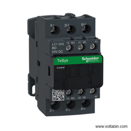
LC1D25BD
| Coil Voltage | 24 V dc |
| Number of Poles | 3 |
| Contact Current Rating | 25 A |
| Power Rating | 11 kW |
| Normal State Configuration | 3NO |
| Contact Voltage Rating | 690 V ac |
| Series | LC1D |
| Range | TeSys D |
| Number Of Auxiliary Contacts | 2 |
| Terminal Type | Screw |
| Width | 45mm |
| Depth | 99mm |
| Maximum Operating Temperature | +60°C |
| Length | 85mm |
| Minimum Operating Temperature | -40°C |
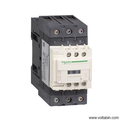
LC1D65AM7
range TeSys
TeSys Decaproduct name TeSys D
TeSys Decaproduct or component type Contactor device short name LC1D contactor application Motor control
Resistive loadutilisation category AC-4
AC-1
AC-3
AC-3epoles description 3P power pole contact composition 3 NO [Ue] rated operational voltage Power circuit: <= 690 V AC 25…400 Hz
Power circuit: <= 300 V DC[Ie] rated operational current 80 A (at <60 °C) at <= 440 V AC AC-1 for power circuit
65 A (at <60 °C) at <= 440 V AC AC-3 for power circuit
65 A (at <60 °C) at <= 440 V AC AC-3e for power circuitmotor power kW 11 kW at 400 V AC 50/60 Hz (AC-4)
18.5 kW at 220…230 V AC 50/60 Hz (AC-3)
30 kW at 380…400 V AC 50/60 Hz (AC-3)
37 kW at 500 V AC 50/60 Hz (AC-3)
37 kW at 660…690 V AC 50/60 Hz (AC-3)
18.5 kW at 220…230 V AC 50/60 Hz (AC-3e)
30 kW at 380…400 V AC 50/60 Hz (AC-3e)
37 kW at 500 V AC 50/60 Hz (AC-3e)
37 kW at 660…690 V AC 50/60 Hz (AC-3e)motor power HP (UL / CSA) 40 hp at 460/480 V AC 50/60 Hz for 3 phases motors
5 hp at 115 V AC 50/60 Hz for 1 phase motors
10 hp at 230/240 V AC 50/60 Hz for 1 phase motors
20 hp at 200/208 V AC 50/60 Hz for 3 phases motors
20 hp at 230/240 V AC 50/60 Hz for 3 phases motors
50 hp at 575/600 V AC 50/60 Hz for 3 phases motorscontrol circuit type AC at 50/60 Hz [Uc] control circuit voltage 220 V AC 50/60 Hz auxiliary contact composition 1 NO + 1 NC [Uimp] rated impulse withstand voltage 6 kV conforming to IEC 60947 overvoltage category III [Ith] conventional free air thermal current 10 A (at 60 °C) for signalling circuit
80 A (at 60 °C) for power circuitIrms rated making capacity 140 A AC for signalling circuit conforming to IEC 60947-5-1
250 A DC for signalling circuit conforming to IEC 60947-5-1
1000 A at 440 V for power circuit conforming to IEC 60947rated breaking capacity 1000 A at 440 V for power circuit conforming to IEC 60947 [Icw] rated short-time withstand current 520 A 40 °C – 10 s for power circuit
900 A 40 °C – 1 s for power circuit
110 A 40 °C – 10 min for power circuit
260 A 40 °C – 1 min for power circuit
100 A – 1 s for signalling circuit
120 A – 500 ms for signalling circuit
140 A – 100 ms for signalling circuitassociated fuse rating 10 A gG for signalling circuit conforming to IEC 60947-5-1
125 A gG at <= 690 V coordination type 1 for power circuit
125 A gG at <= 690 V coordination type 2 for power circuitaverage impedance 1.5 mOhm – Ith 80 A 50 Hz for power circuit [Ui] rated insulation voltage Power circuit: 600 V CSA certified
Power circuit: 600 V UL certified
Signalling circuit: 690 V conforming to IEC 60947-1
Signalling circuit: 600 V CSA certified
Signalling circuit: 600 V UL certified
Power circuit: 690 V conforming to IEC 60947-4-1electrical durability 1.4 Mcycles 80 A AC-1 at Ue <= 440 V
1.45 Mcycles 65 A AC-3 at Ue <= 440 V
1.45 Mcycles 65 A AC-3e at Ue <= 440 Vpower dissipation per pole 9.6 W AC-1
6.3 W AC-3
6.3 W AC-3eFront cover With mounting support Rail
Platestandards CSA C22.2 No 14
EN 60947-4-1
EN 60947-5-1
IEC 60947-4-1
IEC 60947-5-1
UL 508
IEC 60335-1product certifications UL
CCC
GOST
CSAconnections – terminals Control circuit: screw clamp terminals 2 cable(s) 1…2.5 mm²flexible with cable end
Control circuit: screw clamp terminals 1 cable(s) 1…4 mm²flexible without cable end
Control circuit: screw clamp terminals 2 cable(s) 1…4 mm²flexible without cable end
Control circuit: screw clamp terminals 1 cable(s) 1…4 mm²flexible with cable end
Control circuit: screw clamp terminals 1 cable(s) 1…4 mm²solid without cable end
Control circuit: screw clamp terminals 2 cable(s) 1…4 mm²solid without cable end
Power circuit: EverLink BTR screw connectors 1 cable(s) 1…35 mm²flexible without cable end
Power circuit: EverLink BTR screw connectors 2 cable(s) 1…25 mm²flexible without cable end
Power circuit: EverLink BTR screw connectors 1 cable(s) 1…35 mm²flexible with cable end
Power circuit: EverLink BTR screw connectors 2 cable(s) 1…25 mm²flexible with cable end
Power circuit: EverLink BTR screw connectors 1 cable(s) 1…35 mm²solid without cable end
Power circuit: EverLink BTR screw connectors 2 cable(s) 1…25 mm²solid without cable endtightening torque Control circuit: 1.7 N.m – on EverLink BTR screw connectors – with screwdriver flat Ø 6 mm
Control circuit: 1.7 N.m – on EverLink BTR screw connectors – with screwdriver Philips No 2
Power circuit: 8 N.m – on EverLink BTR screw connectors – cable 25…35 mm² hexagonal screw head 4 mm
Power circuit: 5 N.m – on EverLink BTR screw connectors – cable 1…25 mm² hexagonal screw head 4 mm
Control circuit: 1.7 N.m – on EverLink BTR screw connectors – with screwdriver pozidriv No 2
Power circuit: 2.5 N.m – on EverLink BTR screw connectors – with screwdriver pozidriv No 2
– on EverLink BTR screw connectorsoperating time 4…19 ms opening
12…26 ms closingsafety reliability level B10d = 1369863 cycles contactor with nominal load conforming to EN/ISO 13849-1
B10d = 20000000 cycles contactor with mechanical load conforming to EN/ISO 13849-1mechanical durability 6 Mcycles maximum operating rate 3600 cyc/h 60 °C coil technology Without built-in suppressor module control circuit voltage limits 0.3…0.6 Uc (-40…70 °C):drop-out AC 50/60 Hz
0.8…1.1 Uc (-40…60 °C):operational AC 50 Hz
0.85…1.1 Uc (-40…60 °C):operational AC 60 Hz
1…1.1 Uc (60…70 °C):operational AC 50/60 Hzinrush power in VA 140 VA 60 Hz cos phi 0.75 (at 20 °C)
160 VA 50 Hz cos phi 0.75 (at 20 °C)hold-in power consumption in VA 13 VA 60 Hz cos phi 0.3 (at 20 °C)
15 VA 50 Hz cos phi 0.3 (at 20 °C)heat dissipation 4…5 W at 50/60 Hz auxiliary contacts type Type mechanically linked 1 NO + 1 NC conforming to IEC 60947-5-1
type mirror contact 1 NC conforming to IEC 60947-4-1signalling circuit frequency 25…400 Hz minimum switching current 5 mA for signalling circuit minimum switching voltage 17 V for signalling circuit non-overlap time 1.5 ms on de-energisation between NC and NO contact
1.5 ms on energisation between NC and NO contactinsulation resistance > 10 MOhm for signalling circuit IP degree of protection IP20 front face conforming to IEC 60529 climatic withstand Conforming to IACS E10
conforming to IEC 60947-1 Annex Q category Dprotective treatment TH conforming to IEC 60068-2-30 pollution degree 3 ambient air temperature for operation -40…60 °C
60…70 °C with deratingambient air temperature for storage -60…80 °C operating altitude 0…3000 m fire resistance 850 °C conforming to IEC 60695-2-1 mechanical robustness Vibrations contactor open: 2 Gn, 5…300 Hz
Vibrations contactor closed: 4 Gn, 5…300 Hz
Shocks contactor closed: 15 Gn for 11 ms
Shocks contactor open: 10 Gn for 11 msheight 122 mm width 55 mm depth 120 mm net weight 0.86 kg
LV429387
range of product
Easy Altivar 610
product or component type
Variable speed drive
product specific application
Fan, pump, compressor, conveyor
device short name
ATV610
variant
Standard version
product destination
Asynchronous motors
mounting mode
Cabinet mount
EMC filter
Integrated conforming to EN/IEC 61800-3 category C3 with 50 m
IP degree of protection
IP20
type of cooling
Forced convection
supply frequency
50…60 Hz +/-5 %
network number of phases
3 phases
[Us] rated supply voltage
380…460 V – 15…10 %
motor power kW
110 kW for normal duty
90 kW for heavy duty
motor power hp
150 hp for normal duty
125 hp for heavy duty
line current
201 A at 380 V (normal duty)
175.7 A at 460 V (normal duty)
170 A at 380 V (heavy duty)
149.1 A at 460 V (heavy duty)
prospective line Isc
50 kA
apparent power
140.0 kVA at 460 V (normal duty)
118.8 kVA at 460 V (heavy duty)
continuous output current
211 A at 2.5 kHz for normal duty
173 A at 2.5 kHz for heavy duty
maximum transient current
232 A during 60 s (normal duty)
260 A during 60 s (heavy duty)
asynchronous motor control profile
Variable torque standard
Optimized torque mode
Constant torque standard
output frequency
0.0001…0.5 kHz
nominal switching frequency
2.5 kHz
switching frequency
1…8 kHz adjustable
number of preset speeds
16 preset speeds
communication port protocol
Modbus serial
option card
Slot A: communication card, Profibus DP V1
Slot A: digital or analog I/O extension card
Slot A: relay output card
output voltage
<= power supply voltage
motor slip compensation
Can be suppressed
Adjustable
Not available in permanent magnet motor law
Automatic whatever the load
acceleration and deceleration ramps
Linear adjustable separately from 0.01 to 9000 s
S, U or customized
braking to standstill
By DC injection
protection type
Thermal protection: motor
Motor phase break: motor
Thermal protection: drive
Overheating: drive
Overcurrent between output phases and earth: drive
Overload of output voltage: drive
Short-circuit protection: drive
Motor phase break: drive
Overvoltages on the DC bus: drive
Line supply overvoltage: drive
Line supply undervoltage: drive
Line supply phase loss: drive
Overspeed: drive
Break on the control circuit: drive
frequency resolution
Display unit: 0.1 Hz
Analog input: 0.012/50 Hz
electrical connection
Control, screw terminal: 0.5…1.5 mm²
Line side, screw terminal: 2 x 50…3 x 120 mm²
Motor, screw terminal: 3 x 50…3 x 120 mm²
connector type
1 RJ45 (on the remote graphic terminal) for Modbus serial
physical interface
2-wire RS 485 for Modbus serial
transmission frame
RTU for Modbus serial
transmission rate
4.8, 9.6, 19.2, 38.4 kbit/s for Modbus serial
type of polarization
No impedance for Modbus serial
number of addresses
1…247 for Modbus serial
method of access
Slave
supply
External supply for digital inputs: 24 V DC (19…30 V), <1.25 mA, protection type: overload and short-circuit protection
Internal supply for reference potentiometer (1 to 10 kOhm): 10.5 V DC +/- 5 %, <10 mA, protection type: overload and short-circuit protection
local signalling
2 LEDs for local diagnostic
1 LED (yellow) for embedded communication status
2 LEDs (dual colour) for communication module status
1 LED (red) for presence of voltage
width
320 mm
height
852 mm
1159 mm with IP21 conformity kit
depth
390 mm
net weight
82 kg
analogue input number
3
analogue input type
AI1, AI2, AI3 software-configurable voltage: 0…10 V DC, impedance: 30 kOhm, resolution 12 bits
AI1, AI2, AI3 software-configurable current: 0…20 mA, impedance: 250 Ohm, resolution 12 bits
AI2, AI3 software-configurable temperature probe or water level sensor
discrete input number
6
discrete input type
DI1…DI6 programmable as logic input, 24 V DC (<= 30 V), impedance: 3.5 kOhm
DI5, DI6 programmable as pulse input: 0…30 kHz, 24 V DC (<= 30 V)
input compatibility
DI1…DI6: logic input level 1 PLC conforming to EN/IEC 61131-2
DI5, DI6: pulse input level 1 PLC conforming to IEC 65A-68
discrete input logic
Positive logic (source): DI1…DI6 configurable logic input, < 5 V (state 0), > 11 V (state 1)
Negative logic (sink): DI1…DI6 configurable logic input, > 16 V (state 0), < 10 V (state 1)
Positive logic (source): DI5, DI6 configurable pulse input, < 0.6 V (state 0), > 2.5 V (state 1)
analogue output number
2
analogue output type
Software-configurable current AQ1, AQ2: 0…20 mA, resolution 10 bits
Software-configurable voltage AQ1, AQ2: 0…10 V DC impedance 470 Ohm, resolution 10 bits
sampling duration
5 ms +/- 0.1 ms (AI1, AI2, AI3) – analog input
2 ms +/- 0.5 ms (DI1…DI6)configurable – discrete input
5 ms +/- 1 ms (DI5, DI6)configurable – pulse input
10 ms +/- 1 ms (AQ1, AQ2) – analog output
accuracy
+/- 0.6 % AI1, AI2, AI3 for a temperature variation 60 °C analog input
+/- 1 % AQ1, AQ2 for a temperature variation 60 °C analog output
linearity error
AI1, AI2, AI3: +/- 0.15 % of maximum value for analog input
AQ1, AQ2: +/- 0.2 % for analog output
relay output number
3
relay output type
Configurable relay logic R1: fault relay NO/NC electrical durability 100000 cycles
Configurable relay logic R2: sequence relay NO electrical durability 100000 cycles
Configurable relay logic R3: sequence relay NO electrical durability 100000 cycles
refresh time
Relay output (R1, R2, R3): 5 ms (+/- 0.5 ms)
minimum switching current
Relay output R1, R2, R3: 5 mA at 24 V DC
maximum switching current
Relay output R1, R2, R3 on resistive load, cos phi = 1: 3 A at 250 V AC
Relay output R1, R2, R3 on resistive load, cos phi = 1: 3 A at 30 V DC
Relay output R1, R2, R3 on inductive load, cos phi = 0.4 and L/R = 7 ms: 2 A at 250 V AC
Relay output R1, R2, R3 on inductive load, cos phi = 0.4 and L/R = 7 ms: 2 A at 30 V DC
isolation
Between power and control terminals
insulation resistance
> 1 MOhm 500 V DC for 1 minute to earth
noise level
76 dB conforming to 86/188/EEC
power dissipation in W
2026 W(forced convection) at 380 V, switching frequency 2.5 kHz
operating position
Vertical +/- 10 degree
electromagnetic compatibility
Electrostatic discharge immunity test level 3 conforming to IEC 61000-4-2
Radiated radio-frequency electromagnetic field immunity test level 3 conforming to IEC 61000-4-3
Electrical fast transient/burst immunity test level 4 conforming to IEC 61000-4-4
1.2/50 µs – 8/20 µs surge immunity test level 3 conforming to IEC 61000-4-5
Conducted radio-frequency immunity test level 3 conforming to IEC 61000-4-6
pollution degree
2 conforming to EN/IEC 61800-5-1
vibration resistance
1.5 mm peak to peak (f= 2…13 Hz) conforming to IEC 60068-2-6
1 gn (f= 13…200 Hz) conforming to IEC 60068-2-6
shock resistance
6 gn for 11 ms conforming to IEC 60068-2-27
relative humidity
5…95 % without condensation conforming to IEC 60068-2-3
ambient air temperature for operation
-15…45 °C (without derating)
45…60 °C (with derating factor)
operating altitude
<= 1000 m without derating
1000…4800 m with current derating 1 % per 100 m
environmental characteristic
Chemical pollution resistance class 3C3 conforming to EN/IEC 60721-3-3
Dust pollution resistance class 3S3 conforming to EN/IEC 60721-3-3
standards
EN/IEC 61800-3
Environment 2 category C3 EN/IEC 61800-3
EN/IEC 61800-5-1
IEC 60721-3
marking
CE
Unit Type of Package 1
PCE
Number of Units in Package 1
1
Package 1 Weight
96.344 kg
Package 1 Height
47 cm
Package 1 width
67 cm
Package 1 Length
103 cm
LV429407
range of product
Easy Altivar 610
product or component type
Variable speed drive
product specific application
Fan, pump, compressor, conveyor
device short name
ATV610
variant
Standard version
product destination
Asynchronous motors
mounting mode
Cabinet mount
EMC filter
Integrated conforming to EN/IEC 61800-3 category C3 with 50 m
IP degree of protection
IP20
type of cooling
Forced convection
supply frequency
50…60 Hz +/-5 %
network number of phases
3 phases
[Us] rated supply voltage
380…460 V – 15…10 %
motor power kW
110 kW for normal duty
90 kW for heavy duty
motor power hp
150 hp for normal duty
125 hp for heavy duty
line current
201 A at 380 V (normal duty)
175.7 A at 460 V (normal duty)
170 A at 380 V (heavy duty)
149.1 A at 460 V (heavy duty)
prospective line Isc
50 kA
apparent power
140.0 kVA at 460 V (normal duty)
118.8 kVA at 460 V (heavy duty)
continuous output current
211 A at 2.5 kHz for normal duty
173 A at 2.5 kHz for heavy duty
maximum transient current
232 A during 60 s (normal duty)
260 A during 60 s (heavy duty)
asynchronous motor control profile
Variable torque standard
Optimized torque mode
Constant torque standard
output frequency
0.0001…0.5 kHz
nominal switching frequency
2.5 kHz
switching frequency
1…8 kHz adjustable
number of preset speeds
16 preset speeds
communication port protocol
Modbus serial
option card
Slot A: communication card, Profibus DP V1
Slot A: digital or analog I/O extension card
Slot A: relay output card
output voltage
<= power supply voltage
motor slip compensation
Can be suppressed
Adjustable
Not available in permanent magnet motor law
Automatic whatever the load
acceleration and deceleration ramps
Linear adjustable separately from 0.01 to 9000 s
S, U or customized
braking to standstill
By DC injection
protection type
Thermal protection: motor
Motor phase break: motor
Thermal protection: drive
Overheating: drive
Overcurrent between output phases and earth: drive
Overload of output voltage: drive
Short-circuit protection: drive
Motor phase break: drive
Overvoltages on the DC bus: drive
Line supply overvoltage: drive
Line supply undervoltage: drive
Line supply phase loss: drive
Overspeed: drive
Break on the control circuit: drive
frequency resolution
Display unit: 0.1 Hz
Analog input: 0.012/50 Hz
electrical connection
Control, screw terminal: 0.5…1.5 mm²
Line side, screw terminal: 2 x 50…3 x 120 mm²
Motor, screw terminal: 3 x 50…3 x 120 mm²
connector type
1 RJ45 (on the remote graphic terminal) for Modbus serial
physical interface
2-wire RS 485 for Modbus serial
transmission frame
RTU for Modbus serial
transmission rate
4.8, 9.6, 19.2, 38.4 kbit/s for Modbus serial
type of polarization
No impedance for Modbus serial
number of addresses
1…247 for Modbus serial
method of access
Slave
supply
External supply for digital inputs: 24 V DC (19…30 V), <1.25 mA, protection type: overload and short-circuit protection
Internal supply for reference potentiometer (1 to 10 kOhm): 10.5 V DC +/- 5 %, <10 mA, protection type: overload and short-circuit protection
local signalling
2 LEDs for local diagnostic
1 LED (yellow) for embedded communication status
2 LEDs (dual colour) for communication module status
1 LED (red) for presence of voltage
width
320 mm
height
852 mm
1159 mm with IP21 conformity kit
depth
390 mm
net weight
82 kg
analogue input number
3
analogue input type
AI1, AI2, AI3 software-configurable voltage: 0…10 V DC, impedance: 30 kOhm, resolution 12 bits
AI1, AI2, AI3 software-configurable current: 0…20 mA, impedance: 250 Ohm, resolution 12 bits
AI2, AI3 software-configurable temperature probe or water level sensor
discrete input number
6
discrete input type
DI1…DI6 programmable as logic input, 24 V DC (<= 30 V), impedance: 3.5 kOhm
DI5, DI6 programmable as pulse input: 0…30 kHz, 24 V DC (<= 30 V)
input compatibility
DI1…DI6: logic input level 1 PLC conforming to EN/IEC 61131-2
DI5, DI6: pulse input level 1 PLC conforming to IEC 65A-68
discrete input logic
Positive logic (source): DI1…DI6 configurable logic input, < 5 V (state 0), > 11 V (state 1)
Negative logic (sink): DI1…DI6 configurable logic input, > 16 V (state 0), < 10 V (state 1)
Positive logic (source): DI5, DI6 configurable pulse input, < 0.6 V (state 0), > 2.5 V (state 1)
analogue output number
2
analogue output type
Software-configurable current AQ1, AQ2: 0…20 mA, resolution 10 bits
Software-configurable voltage AQ1, AQ2: 0…10 V DC impedance 470 Ohm, resolution 10 bits
sampling duration
5 ms +/- 0.1 ms (AI1, AI2, AI3) – analog input
2 ms +/- 0.5 ms (DI1…DI6)configurable – discrete input
5 ms +/- 1 ms (DI5, DI6)configurable – pulse input
10 ms +/- 1 ms (AQ1, AQ2) – analog output
accuracy
+/- 0.6 % AI1, AI2, AI3 for a temperature variation 60 °C analog input
+/- 1 % AQ1, AQ2 for a temperature variation 60 °C analog output
linearity error
AI1, AI2, AI3: +/- 0.15 % of maximum value for analog input
AQ1, AQ2: +/- 0.2 % for analog output
relay output number
3
relay output type
Configurable relay logic R1: fault relay NO/NC electrical durability 100000 cycles
Configurable relay logic R2: sequence relay NO electrical durability 100000 cycles
Configurable relay logic R3: sequence relay NO electrical durability 100000 cycles
refresh time
Relay output (R1, R2, R3): 5 ms (+/- 0.5 ms)
minimum switching current
Relay output R1, R2, R3: 5 mA at 24 V DC
maximum switching current
Relay output R1, R2, R3 on resistive load, cos phi = 1: 3 A at 250 V AC
Relay output R1, R2, R3 on resistive load, cos phi = 1: 3 A at 30 V DC
Relay output R1, R2, R3 on inductive load, cos phi = 0.4 and L/R = 7 ms: 2 A at 250 V AC
Relay output R1, R2, R3 on inductive load, cos phi = 0.4 and L/R = 7 ms: 2 A at 30 V DC
isolation
Between power and control terminals
insulation resistance
> 1 MOhm 500 V DC for 1 minute to earth
noise level
76 dB conforming to 86/188/EEC
power dissipation in W
2026 W(forced convection) at 380 V, switching frequency 2.5 kHz
operating position
Vertical +/- 10 degree
electromagnetic compatibility
Electrostatic discharge immunity test level 3 conforming to IEC 61000-4-2
Radiated radio-frequency electromagnetic field immunity test level 3 conforming to IEC 61000-4-3
Electrical fast transient/burst immunity test level 4 conforming to IEC 61000-4-4
1.2/50 µs – 8/20 µs surge immunity test level 3 conforming to IEC 61000-4-5
Conducted radio-frequency immunity test level 3 conforming to IEC 61000-4-6
pollution degree
2 conforming to EN/IEC 61800-5-1
vibration resistance
1.5 mm peak to peak (f= 2…13 Hz) conforming to IEC 60068-2-6
1 gn (f= 13…200 Hz) conforming to IEC 60068-2-6
shock resistance
6 gn for 11 ms conforming to IEC 60068-2-27
relative humidity
5…95 % without condensation conforming to IEC 60068-2-3
ambient air temperature for operation
-15…45 °C (without derating)
45…60 °C (with derating factor)
operating altitude
<= 1000 m without derating
1000…4800 m with current derating 1 % per 100 m
environmental characteristic
Chemical pollution resistance class 3C3 conforming to EN/IEC 60721-3-3
Dust pollution resistance class 3S3 conforming to EN/IEC 60721-3-3
standards
EN/IEC 61800-3
Environment 2 category C3 EN/IEC 61800-3
EN/IEC 61800-5-1
IEC 60721-3
marking
CE
Unit Type of Package 1
PCE
Number of Units in Package 1
1
Package 1 Weight
96.344 kg
Package 1 Height
47 cm
Package 1 width
67 cm
Package 1 Length
103 cm
LV429566
range of product
Easy Altivar 610
product or component type
Variable speed drive
product specific application
Fan, pump, compressor, conveyor
device short name
ATV610
variant
Standard version
product destination
Asynchronous motors
mounting mode
Cabinet mount
EMC filter
Integrated conforming to EN/IEC 61800-3 category C3 with 50 m
IP degree of protection
IP20
type of cooling
Forced convection
supply frequency
50…60 Hz +/-5 %
network number of phases
3 phases
[Us] rated supply voltage
380…460 V – 15…10 %
motor power kW
110 kW for normal duty
90 kW for heavy duty
motor power hp
150 hp for normal duty
125 hp for heavy duty
line current
201 A at 380 V (normal duty)
175.7 A at 460 V (normal duty)
170 A at 380 V (heavy duty)
149.1 A at 460 V (heavy duty)
prospective line Isc
50 kA
apparent power
140.0 kVA at 460 V (normal duty)
118.8 kVA at 460 V (heavy duty)
continuous output current
211 A at 2.5 kHz for normal duty
173 A at 2.5 kHz for heavy duty
maximum transient current
232 A during 60 s (normal duty)
260 A during 60 s (heavy duty)
asynchronous motor control profile
Variable torque standard
Optimized torque mode
Constant torque standard
output frequency
0.0001…0.5 kHz
nominal switching frequency
2.5 kHz
switching frequency
1…8 kHz adjustable
number of preset speeds
16 preset speeds
communication port protocol
Modbus serial
option card
Slot A: communication card, Profibus DP V1
Slot A: digital or analog I/O extension card
Slot A: relay output card
output voltage
<= power supply voltage
motor slip compensation
Can be suppressed
Adjustable
Not available in permanent magnet motor law
Automatic whatever the load
acceleration and deceleration ramps
Linear adjustable separately from 0.01 to 9000 s
S, U or customized
braking to standstill
By DC injection
protection type
Thermal protection: motor
Motor phase break: motor
Thermal protection: drive
Overheating: drive
Overcurrent between output phases and earth: drive
Overload of output voltage: drive
Short-circuit protection: drive
Motor phase break: drive
Overvoltages on the DC bus: drive
Line supply overvoltage: drive
Line supply undervoltage: drive
Line supply phase loss: drive
Overspeed: drive
Break on the control circuit: drive
frequency resolution
Display unit: 0.1 Hz
Analog input: 0.012/50 Hz
electrical connection
Control, screw terminal: 0.5…1.5 mm²
Line side, screw terminal: 2 x 50…3 x 120 mm²
Motor, screw terminal: 3 x 50…3 x 120 mm²
connector type
1 RJ45 (on the remote graphic terminal) for Modbus serial
physical interface
2-wire RS 485 for Modbus serial
transmission frame
RTU for Modbus serial
transmission rate
4.8, 9.6, 19.2, 38.4 kbit/s for Modbus serial
type of polarization
No impedance for Modbus serial
number of addresses
1…247 for Modbus serial
method of access
Slave
supply
External supply for digital inputs: 24 V DC (19…30 V), <1.25 mA, protection type: overload and short-circuit protection
Internal supply for reference potentiometer (1 to 10 kOhm): 10.5 V DC +/- 5 %, <10 mA, protection type: overload and short-circuit protection
local signalling
2 LEDs for local diagnostic
1 LED (yellow) for embedded communication status
2 LEDs (dual colour) for communication module status
1 LED (red) for presence of voltage
width
320 mm
height
852 mm
1159 mm with IP21 conformity kit
depth
390 mm
net weight
82 kg
analogue input number
3
analogue input type
AI1, AI2, AI3 software-configurable voltage: 0…10 V DC, impedance: 30 kOhm, resolution 12 bits
AI1, AI2, AI3 software-configurable current: 0…20 mA, impedance: 250 Ohm, resolution 12 bits
AI2, AI3 software-configurable temperature probe or water level sensor
discrete input number
6
discrete input type
DI1…DI6 programmable as logic input, 24 V DC (<= 30 V), impedance: 3.5 kOhm
DI5, DI6 programmable as pulse input: 0…30 kHz, 24 V DC (<= 30 V)
input compatibility
DI1…DI6: logic input level 1 PLC conforming to EN/IEC 61131-2
DI5, DI6: pulse input level 1 PLC conforming to IEC 65A-68
discrete input logic
Positive logic (source): DI1…DI6 configurable logic input, < 5 V (state 0), > 11 V (state 1)
Negative logic (sink): DI1…DI6 configurable logic input, > 16 V (state 0), < 10 V (state 1)
Positive logic (source): DI5, DI6 configurable pulse input, < 0.6 V (state 0), > 2.5 V (state 1)
analogue output number
2
analogue output type
Software-configurable current AQ1, AQ2: 0…20 mA, resolution 10 bits
Software-configurable voltage AQ1, AQ2: 0…10 V DC impedance 470 Ohm, resolution 10 bits
sampling duration
5 ms +/- 0.1 ms (AI1, AI2, AI3) – analog input
2 ms +/- 0.5 ms (DI1…DI6)configurable – discrete input
5 ms +/- 1 ms (DI5, DI6)configurable – pulse input
10 ms +/- 1 ms (AQ1, AQ2) – analog output
accuracy
+/- 0.6 % AI1, AI2, AI3 for a temperature variation 60 °C analog input
+/- 1 % AQ1, AQ2 for a temperature variation 60 °C analog output
linearity error
AI1, AI2, AI3: +/- 0.15 % of maximum value for analog input
AQ1, AQ2: +/- 0.2 % for analog output
relay output number
3
relay output type
Configurable relay logic R1: fault relay NO/NC electrical durability 100000 cycles
Configurable relay logic R2: sequence relay NO electrical durability 100000 cycles
Configurable relay logic R3: sequence relay NO electrical durability 100000 cycles
refresh time
Relay output (R1, R2, R3): 5 ms (+/- 0.5 ms)
minimum switching current
Relay output R1, R2, R3: 5 mA at 24 V DC
maximum switching current
Relay output R1, R2, R3 on resistive load, cos phi = 1: 3 A at 250 V AC
Relay output R1, R2, R3 on resistive load, cos phi = 1: 3 A at 30 V DC
Relay output R1, R2, R3 on inductive load, cos phi = 0.4 and L/R = 7 ms: 2 A at 250 V AC
Relay output R1, R2, R3 on inductive load, cos phi = 0.4 and L/R = 7 ms: 2 A at 30 V DC
isolation
Between power and control terminals
insulation resistance
> 1 MOhm 500 V DC for 1 minute to earth
noise level
76 dB conforming to 86/188/EEC
power dissipation in W
2026 W(forced convection) at 380 V, switching frequency 2.5 kHz
operating position
Vertical +/- 10 degree
electromagnetic compatibility
Electrostatic discharge immunity test level 3 conforming to IEC 61000-4-2
Radiated radio-frequency electromagnetic field immunity test level 3 conforming to IEC 61000-4-3
Electrical fast transient/burst immunity test level 4 conforming to IEC 61000-4-4
1.2/50 µs – 8/20 µs surge immunity test level 3 conforming to IEC 61000-4-5
Conducted radio-frequency immunity test level 3 conforming to IEC 61000-4-6
pollution degree
2 conforming to EN/IEC 61800-5-1
vibration resistance
1.5 mm peak to peak (f= 2…13 Hz) conforming to IEC 60068-2-6
1 gn (f= 13…200 Hz) conforming to IEC 60068-2-6
shock resistance
6 gn for 11 ms conforming to IEC 60068-2-27
relative humidity
5…95 % without condensation conforming to IEC 60068-2-3
ambient air temperature for operation
-15…45 °C (without derating)
45…60 °C (with derating factor)
operating altitude
<= 1000 m without derating
1000…4800 m with current derating 1 % per 100 m
environmental characteristic
Chemical pollution resistance class 3C3 conforming to EN/IEC 60721-3-3
Dust pollution resistance class 3S3 conforming to EN/IEC 60721-3-3
standards
EN/IEC 61800-3
Environment 2 category C3 EN/IEC 61800-3
EN/IEC 61800-5-1
IEC 60721-3
marking
CE
Unit Type of Package 1
PCE
Number of Units in Package 1
1
Package 1 Weight
96.344 kg
Package 1 Height
47 cm
Package 1 width
67 cm
Package 1 Length
103 cm

LV429567
range of product
Easy Altivar 610
product or component type
Variable speed drive
product specific application
Fan, pump, compressor, conveyor
device short name
ATV610
variant
Standard version
product destination
Asynchronous motors
mounting mode
Cabinet mount
EMC filter
Integrated conforming to EN/IEC 61800-3 category C3 with 50 m
IP degree of protection
IP20
type of cooling
Forced convection
supply frequency
50…60 Hz +/-5 %
network number of phases
3 phases
[Us] rated supply voltage
380…460 V – 15…10 %
motor power kW
110 kW for normal duty
90 kW for heavy duty
motor power hp
150 hp for normal duty
125 hp for heavy duty
line current
201 A at 380 V (normal duty)
175.7 A at 460 V (normal duty)
170 A at 380 V (heavy duty)
149.1 A at 460 V (heavy duty)
prospective line Isc
50 kA
apparent power
140.0 kVA at 460 V (normal duty)
118.8 kVA at 460 V (heavy duty)
continuous output current
211 A at 2.5 kHz for normal duty
173 A at 2.5 kHz for heavy duty
maximum transient current
232 A during 60 s (normal duty)
260 A during 60 s (heavy duty)
asynchronous motor control profile
Variable torque standard
Optimized torque mode
Constant torque standard
output frequency
0.0001…0.5 kHz
nominal switching frequency
2.5 kHz
switching frequency
1…8 kHz adjustable
number of preset speeds
16 preset speeds
communication port protocol
Modbus serial
option card
Slot A: communication card, Profibus DP V1
Slot A: digital or analog I/O extension card
Slot A: relay output card
output voltage
<= power supply voltage
motor slip compensation
Can be suppressed
Adjustable
Not available in permanent magnet motor law
Automatic whatever the load
acceleration and deceleration ramps
Linear adjustable separately from 0.01 to 9000 s
S, U or customized
braking to standstill
By DC injection
protection type
Thermal protection: motor
Motor phase break: motor
Thermal protection: drive
Overheating: drive
Overcurrent between output phases and earth: drive
Overload of output voltage: drive
Short-circuit protection: drive
Motor phase break: drive
Overvoltages on the DC bus: drive
Line supply overvoltage: drive
Line supply undervoltage: drive
Line supply phase loss: drive
Overspeed: drive
Break on the control circuit: drive
frequency resolution
Display unit: 0.1 Hz
Analog input: 0.012/50 Hz
electrical connection
Control, screw terminal: 0.5…1.5 mm²
Line side, screw terminal: 2 x 50…3 x 120 mm²
Motor, screw terminal: 3 x 50…3 x 120 mm²
connector type
1 RJ45 (on the remote graphic terminal) for Modbus serial
physical interface
2-wire RS 485 for Modbus serial
transmission frame
RTU for Modbus serial
transmission rate
4.8, 9.6, 19.2, 38.4 kbit/s for Modbus serial
type of polarization
No impedance for Modbus serial
number of addresses
1…247 for Modbus serial
method of access
Slave
supply
External supply for digital inputs: 24 V DC (19…30 V), <1.25 mA, protection type: overload and short-circuit protection
Internal supply for reference potentiometer (1 to 10 kOhm): 10.5 V DC +/- 5 %, <10 mA, protection type: overload and short-circuit protection
local signalling
2 LEDs for local diagnostic
1 LED (yellow) for embedded communication status
2 LEDs (dual colour) for communication module status
1 LED (red) for presence of voltage
width
320 mm
height
852 mm
1159 mm with IP21 conformity kit
depth
390 mm
net weight
82 kg
analogue input number
3
analogue input type
AI1, AI2, AI3 software-configurable voltage: 0…10 V DC, impedance: 30 kOhm, resolution 12 bits
AI1, AI2, AI3 software-configurable current: 0…20 mA, impedance: 250 Ohm, resolution 12 bits
AI2, AI3 software-configurable temperature probe or water level sensor
discrete input number
6
discrete input type
DI1…DI6 programmable as logic input, 24 V DC (<= 30 V), impedance: 3.5 kOhm
DI5, DI6 programmable as pulse input: 0…30 kHz, 24 V DC (<= 30 V)
input compatibility
DI1…DI6: logic input level 1 PLC conforming to EN/IEC 61131-2
DI5, DI6: pulse input level 1 PLC conforming to IEC 65A-68
discrete input logic
Positive logic (source): DI1…DI6 configurable logic input, < 5 V (state 0), > 11 V (state 1)
Negative logic (sink): DI1…DI6 configurable logic input, > 16 V (state 0), < 10 V (state 1)
Positive logic (source): DI5, DI6 configurable pulse input, < 0.6 V (state 0), > 2.5 V (state 1)
analogue output number
2
analogue output type
Software-configurable current AQ1, AQ2: 0…20 mA, resolution 10 bits
Software-configurable voltage AQ1, AQ2: 0…10 V DC impedance 470 Ohm, resolution 10 bits
sampling duration
5 ms +/- 0.1 ms (AI1, AI2, AI3) – analog input
2 ms +/- 0.5 ms (DI1…DI6)configurable – discrete input
5 ms +/- 1 ms (DI5, DI6)configurable – pulse input
10 ms +/- 1 ms (AQ1, AQ2) – analog output
accuracy
+/- 0.6 % AI1, AI2, AI3 for a temperature variation 60 °C analog input
+/- 1 % AQ1, AQ2 for a temperature variation 60 °C analog output
linearity error
AI1, AI2, AI3: +/- 0.15 % of maximum value for analog input
AQ1, AQ2: +/- 0.2 % for analog output
relay output number
3
relay output type
Configurable relay logic R1: fault relay NO/NC electrical durability 100000 cycles
Configurable relay logic R2: sequence relay NO electrical durability 100000 cycles
Configurable relay logic R3: sequence relay NO electrical durability 100000 cycles
refresh time
Relay output (R1, R2, R3): 5 ms (+/- 0.5 ms)
minimum switching current
Relay output R1, R2, R3: 5 mA at 24 V DC
maximum switching current
Relay output R1, R2, R3 on resistive load, cos phi = 1: 3 A at 250 V AC
Relay output R1, R2, R3 on resistive load, cos phi = 1: 3 A at 30 V DC
Relay output R1, R2, R3 on inductive load, cos phi = 0.4 and L/R = 7 ms: 2 A at 250 V AC
Relay output R1, R2, R3 on inductive load, cos phi = 0.4 and L/R = 7 ms: 2 A at 30 V DC
isolation
Between power and control terminals
insulation resistance
> 1 MOhm 500 V DC for 1 minute to earth
noise level
76 dB conforming to 86/188/EEC
power dissipation in W
2026 W(forced convection) at 380 V, switching frequency 2.5 kHz
operating position
Vertical +/- 10 degree
electromagnetic compatibility
Electrostatic discharge immunity test level 3 conforming to IEC 61000-4-2
Radiated radio-frequency electromagnetic field immunity test level 3 conforming to IEC 61000-4-3
Electrical fast transient/burst immunity test level 4 conforming to IEC 61000-4-4
1.2/50 µs – 8/20 µs surge immunity test level 3 conforming to IEC 61000-4-5
Conducted radio-frequency immunity test level 3 conforming to IEC 61000-4-6
pollution degree
2 conforming to EN/IEC 61800-5-1
vibration resistance
1.5 mm peak to peak (f= 2…13 Hz) conforming to IEC 60068-2-6
1 gn (f= 13…200 Hz) conforming to IEC 60068-2-6
shock resistance
6 gn for 11 ms conforming to IEC 60068-2-27
relative humidity
5…95 % without condensation conforming to IEC 60068-2-3
ambient air temperature for operation
-15…45 °C (without derating)
45…60 °C (with derating factor)
operating altitude
<= 1000 m without derating
1000…4800 m with current derating 1 % per 100 m
environmental characteristic
Chemical pollution resistance class 3C3 conforming to EN/IEC 60721-3-3
Dust pollution resistance class 3S3 conforming to EN/IEC 60721-3-3
standards
EN/IEC 61800-3
Environment 2 category C3 EN/IEC 61800-3
EN/IEC 61800-5-1
IEC 60721-3
marking
CE
Unit Type of Package 1
PCE
Number of Units in Package 1
1
Package 1 Weight
96.344 kg
Package 1 Height
47 cm
Package 1 width
67 cm
Package 1 Length
103 cm
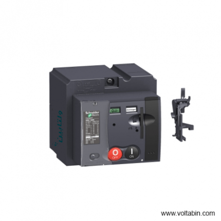
LV431541
range of product
Easy Altivar 610
product or component type
Variable speed drive
product specific application
Fan, pump, compressor, conveyor
device short name
ATV610
variant
Standard version
product destination
Asynchronous motors
mounting mode
Cabinet mount
EMC filter
Integrated conforming to EN/IEC 61800-3 category C3 with 50 m
IP degree of protection
IP20
type of cooling
Forced convection
supply frequency
50…60 Hz +/-5 %
network number of phases
3 phases
[Us] rated supply voltage
380…460 V – 15…10 %
motor power kW
110 kW for normal duty
90 kW for heavy duty
motor power hp
150 hp for normal duty
125 hp for heavy duty
line current
201 A at 380 V (normal duty)
175.7 A at 460 V (normal duty)
170 A at 380 V (heavy duty)
149.1 A at 460 V (heavy duty)
prospective line Isc
50 kA
apparent power
140.0 kVA at 460 V (normal duty)
118.8 kVA at 460 V (heavy duty)
continuous output current
211 A at 2.5 kHz for normal duty
173 A at 2.5 kHz for heavy duty
maximum transient current
232 A during 60 s (normal duty)
260 A during 60 s (heavy duty)
asynchronous motor control profile
Variable torque standard
Optimized torque mode
Constant torque standard
output frequency
0.0001…0.5 kHz
nominal switching frequency
2.5 kHz
switching frequency
1…8 kHz adjustable
number of preset speeds
16 preset speeds
communication port protocol
Modbus serial
option card
Slot A: communication card, Profibus DP V1
Slot A: digital or analog I/O extension card
Slot A: relay output card
output voltage
<= power supply voltage
motor slip compensation
Can be suppressed
Adjustable
Not available in permanent magnet motor law
Automatic whatever the load
acceleration and deceleration ramps
Linear adjustable separately from 0.01 to 9000 s
S, U or customized
braking to standstill
By DC injection
protection type
Thermal protection: motor
Motor phase break: motor
Thermal protection: drive
Overheating: drive
Overcurrent between output phases and earth: drive
Overload of output voltage: drive
Short-circuit protection: drive
Motor phase break: drive
Overvoltages on the DC bus: drive
Line supply overvoltage: drive
Line supply undervoltage: drive
Line supply phase loss: drive
Overspeed: drive
Break on the control circuit: drive
frequency resolution
Display unit: 0.1 Hz
Analog input: 0.012/50 Hz
electrical connection
Control, screw terminal: 0.5…1.5 mm²
Line side, screw terminal: 2 x 50…3 x 120 mm²
Motor, screw terminal: 3 x 50…3 x 120 mm²
connector type
1 RJ45 (on the remote graphic terminal) for Modbus serial
physical interface
2-wire RS 485 for Modbus serial
transmission frame
RTU for Modbus serial
transmission rate
4.8, 9.6, 19.2, 38.4 kbit/s for Modbus serial
type of polarization
No impedance for Modbus serial
number of addresses
1…247 for Modbus serial
method of access
Slave
supply
External supply for digital inputs: 24 V DC (19…30 V), <1.25 mA, protection type: overload and short-circuit protection
Internal supply for reference potentiometer (1 to 10 kOhm): 10.5 V DC +/- 5 %, <10 mA, protection type: overload and short-circuit protection
local signalling
2 LEDs for local diagnostic
1 LED (yellow) for embedded communication status
2 LEDs (dual colour) for communication module status
1 LED (red) for presence of voltage
width
320 mm
height
852 mm
1159 mm with IP21 conformity kit
depth
390 mm
net weight
82 kg
analogue input number
3
analogue input type
AI1, AI2, AI3 software-configurable voltage: 0…10 V DC, impedance: 30 kOhm, resolution 12 bits
AI1, AI2, AI3 software-configurable current: 0…20 mA, impedance: 250 Ohm, resolution 12 bits
AI2, AI3 software-configurable temperature probe or water level sensor
discrete input number
6
discrete input type
DI1…DI6 programmable as logic input, 24 V DC (<= 30 V), impedance: 3.5 kOhm
DI5, DI6 programmable as pulse input: 0…30 kHz, 24 V DC (<= 30 V)
input compatibility
DI1…DI6: logic input level 1 PLC conforming to EN/IEC 61131-2
DI5, DI6: pulse input level 1 PLC conforming to IEC 65A-68
discrete input logic
Positive logic (source): DI1…DI6 configurable logic input, < 5 V (state 0), > 11 V (state 1)
Negative logic (sink): DI1…DI6 configurable logic input, > 16 V (state 0), < 10 V (state 1)
Positive logic (source): DI5, DI6 configurable pulse input, < 0.6 V (state 0), > 2.5 V (state 1)
analogue output number
2
analogue output type
Software-configurable current AQ1, AQ2: 0…20 mA, resolution 10 bits
Software-configurable voltage AQ1, AQ2: 0…10 V DC impedance 470 Ohm, resolution 10 bits
sampling duration
5 ms +/- 0.1 ms (AI1, AI2, AI3) – analog input
2 ms +/- 0.5 ms (DI1…DI6)configurable – discrete input
5 ms +/- 1 ms (DI5, DI6)configurable – pulse input
10 ms +/- 1 ms (AQ1, AQ2) – analog output
accuracy
+/- 0.6 % AI1, AI2, AI3 for a temperature variation 60 °C analog input
+/- 1 % AQ1, AQ2 for a temperature variation 60 °C analog output
linearity error
AI1, AI2, AI3: +/- 0.15 % of maximum value for analog input
AQ1, AQ2: +/- 0.2 % for analog output
relay output number
3
relay output type
Configurable relay logic R1: fault relay NO/NC electrical durability 100000 cycles
Configurable relay logic R2: sequence relay NO electrical durability 100000 cycles
Configurable relay logic R3: sequence relay NO electrical durability 100000 cycles
refresh time
Relay output (R1, R2, R3): 5 ms (+/- 0.5 ms)
minimum switching current
Relay output R1, R2, R3: 5 mA at 24 V DC
maximum switching current
Relay output R1, R2, R3 on resistive load, cos phi = 1: 3 A at 250 V AC
Relay output R1, R2, R3 on resistive load, cos phi = 1: 3 A at 30 V DC
Relay output R1, R2, R3 on inductive load, cos phi = 0.4 and L/R = 7 ms: 2 A at 250 V AC
Relay output R1, R2, R3 on inductive load, cos phi = 0.4 and L/R = 7 ms: 2 A at 30 V DC
isolation
Between power and control terminals
insulation resistance
> 1 MOhm 500 V DC for 1 minute to earth
noise level
76 dB conforming to 86/188/EEC
power dissipation in W
2026 W(forced convection) at 380 V, switching frequency 2.5 kHz
operating position
Vertical +/- 10 degree
electromagnetic compatibility
Electrostatic discharge immunity test level 3 conforming to IEC 61000-4-2
Radiated radio-frequency electromagnetic field immunity test level 3 conforming to IEC 61000-4-3
Electrical fast transient/burst immunity test level 4 conforming to IEC 61000-4-4
1.2/50 µs – 8/20 µs surge immunity test level 3 conforming to IEC 61000-4-5
Conducted radio-frequency immunity test level 3 conforming to IEC 61000-4-6
pollution degree
2 conforming to EN/IEC 61800-5-1
vibration resistance
1.5 mm peak to peak (f= 2…13 Hz) conforming to IEC 60068-2-6
1 gn (f= 13…200 Hz) conforming to IEC 60068-2-6
shock resistance
6 gn for 11 ms conforming to IEC 60068-2-27
relative humidity
5…95 % without condensation conforming to IEC 60068-2-3
ambient air temperature for operation
-15…45 °C (without derating)
45…60 °C (with derating factor)
operating altitude
<= 1000 m without derating
1000…4800 m with current derating 1 % per 100 m
environmental characteristic
Chemical pollution resistance class 3C3 conforming to EN/IEC 60721-3-3
Dust pollution resistance class 3S3 conforming to EN/IEC 60721-3-3
standards
EN/IEC 61800-3
Environment 2 category C3 EN/IEC 61800-3
EN/IEC 61800-5-1
IEC 60721-3
marking
CE
Unit Type of Package 1
PCE
Number of Units in Package 1
1
Package 1 Weight
96.344 kg
Package 1 Height
47 cm
Package 1 width
67 cm
Package 1 Length
103 cm
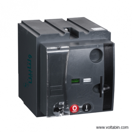
LV432641
range of product
Easy Altivar 610
product or component type
Variable speed drive
product specific application
Fan, pump, compressor, conveyor
device short name
ATV610
variant
Standard version
product destination
Asynchronous motors
mounting mode
Cabinet mount
EMC filter
Integrated conforming to EN/IEC 61800-3 category C3 with 50 m
IP degree of protection
IP20
type of cooling
Forced convection
supply frequency
50…60 Hz +/-5 %
network number of phases
3 phases
[Us] rated supply voltage
380…460 V – 15…10 %
motor power kW
110 kW for normal duty
90 kW for heavy duty
motor power hp
150 hp for normal duty
125 hp for heavy duty
line current
201 A at 380 V (normal duty)
175.7 A at 460 V (normal duty)
170 A at 380 V (heavy duty)
149.1 A at 460 V (heavy duty)
prospective line Isc
50 kA
apparent power
140.0 kVA at 460 V (normal duty)
118.8 kVA at 460 V (heavy duty)
continuous output current
211 A at 2.5 kHz for normal duty
173 A at 2.5 kHz for heavy duty
maximum transient current
232 A during 60 s (normal duty)
260 A during 60 s (heavy duty)
asynchronous motor control profile
Variable torque standard
Optimized torque mode
Constant torque standard
output frequency
0.0001…0.5 kHz
nominal switching frequency
2.5 kHz
switching frequency
1…8 kHz adjustable
number of preset speeds
16 preset speeds
communication port protocol
Modbus serial
option card
Slot A: communication card, Profibus DP V1
Slot A: digital or analog I/O extension card
Slot A: relay output card
output voltage
<= power supply voltage
motor slip compensation
Can be suppressed
Adjustable
Not available in permanent magnet motor law
Automatic whatever the load
acceleration and deceleration ramps
Linear adjustable separately from 0.01 to 9000 s
S, U or customized
braking to standstill
By DC injection
protection type
Thermal protection: motor
Motor phase break: motor
Thermal protection: drive
Overheating: drive
Overcurrent between output phases and earth: drive
Overload of output voltage: drive
Short-circuit protection: drive
Motor phase break: drive
Overvoltages on the DC bus: drive
Line supply overvoltage: drive
Line supply undervoltage: drive
Line supply phase loss: drive
Overspeed: drive
Break on the control circuit: drive
frequency resolution
Display unit: 0.1 Hz
Analog input: 0.012/50 Hz
electrical connection
Control, screw terminal: 0.5…1.5 mm²
Line side, screw terminal: 2 x 50…3 x 120 mm²
Motor, screw terminal: 3 x 50…3 x 120 mm²
connector type
1 RJ45 (on the remote graphic terminal) for Modbus serial
physical interface
2-wire RS 485 for Modbus serial
transmission frame
RTU for Modbus serial
transmission rate
4.8, 9.6, 19.2, 38.4 kbit/s for Modbus serial
type of polarization
No impedance for Modbus serial
number of addresses
1…247 for Modbus serial
method of access
Slave
supply
External supply for digital inputs: 24 V DC (19…30 V), <1.25 mA, protection type: overload and short-circuit protection
Internal supply for reference potentiometer (1 to 10 kOhm): 10.5 V DC +/- 5 %, <10 mA, protection type: overload and short-circuit protection
local signalling
2 LEDs for local diagnostic
1 LED (yellow) for embedded communication status
2 LEDs (dual colour) for communication module status
1 LED (red) for presence of voltage
width
320 mm
height
852 mm
1159 mm with IP21 conformity kit
depth
390 mm
net weight
82 kg
analogue input number
3
analogue input type
AI1, AI2, AI3 software-configurable voltage: 0…10 V DC, impedance: 30 kOhm, resolution 12 bits
AI1, AI2, AI3 software-configurable current: 0…20 mA, impedance: 250 Ohm, resolution 12 bits
AI2, AI3 software-configurable temperature probe or water level sensor
discrete input number
6
discrete input type
DI1…DI6 programmable as logic input, 24 V DC (<= 30 V), impedance: 3.5 kOhm
DI5, DI6 programmable as pulse input: 0…30 kHz, 24 V DC (<= 30 V)
input compatibility
DI1…DI6: logic input level 1 PLC conforming to EN/IEC 61131-2
DI5, DI6: pulse input level 1 PLC conforming to IEC 65A-68
discrete input logic
Positive logic (source): DI1…DI6 configurable logic input, < 5 V (state 0), > 11 V (state 1)
Negative logic (sink): DI1…DI6 configurable logic input, > 16 V (state 0), < 10 V (state 1)
Positive logic (source): DI5, DI6 configurable pulse input, < 0.6 V (state 0), > 2.5 V (state 1)
analogue output number
2
analogue output type
Software-configurable current AQ1, AQ2: 0…20 mA, resolution 10 bits
Software-configurable voltage AQ1, AQ2: 0…10 V DC impedance 470 Ohm, resolution 10 bits
sampling duration
5 ms +/- 0.1 ms (AI1, AI2, AI3) – analog input
2 ms +/- 0.5 ms (DI1…DI6)configurable – discrete input
5 ms +/- 1 ms (DI5, DI6)configurable – pulse input
10 ms +/- 1 ms (AQ1, AQ2) – analog output
accuracy
+/- 0.6 % AI1, AI2, AI3 for a temperature variation 60 °C analog input
+/- 1 % AQ1, AQ2 for a temperature variation 60 °C analog output
linearity error
AI1, AI2, AI3: +/- 0.15 % of maximum value for analog input
AQ1, AQ2: +/- 0.2 % for analog output
relay output number
3
relay output type
Configurable relay logic R1: fault relay NO/NC electrical durability 100000 cycles
Configurable relay logic R2: sequence relay NO electrical durability 100000 cycles
Configurable relay logic R3: sequence relay NO electrical durability 100000 cycles
refresh time
Relay output (R1, R2, R3): 5 ms (+/- 0.5 ms)
minimum switching current
Relay output R1, R2, R3: 5 mA at 24 V DC
maximum switching current
Relay output R1, R2, R3 on resistive load, cos phi = 1: 3 A at 250 V AC
Relay output R1, R2, R3 on resistive load, cos phi = 1: 3 A at 30 V DC
Relay output R1, R2, R3 on inductive load, cos phi = 0.4 and L/R = 7 ms: 2 A at 250 V AC
Relay output R1, R2, R3 on inductive load, cos phi = 0.4 and L/R = 7 ms: 2 A at 30 V DC
isolation
Between power and control terminals
insulation resistance
> 1 MOhm 500 V DC for 1 minute to earth
noise level
76 dB conforming to 86/188/EEC
power dissipation in W
2026 W(forced convection) at 380 V, switching frequency 2.5 kHz
operating position
Vertical +/- 10 degree
electromagnetic compatibility
Electrostatic discharge immunity test level 3 conforming to IEC 61000-4-2
Radiated radio-frequency electromagnetic field immunity test level 3 conforming to IEC 61000-4-3
Electrical fast transient/burst immunity test level 4 conforming to IEC 61000-4-4
1.2/50 µs – 8/20 µs surge immunity test level 3 conforming to IEC 61000-4-5
Conducted radio-frequency immunity test level 3 conforming to IEC 61000-4-6
pollution degree
2 conforming to EN/IEC 61800-5-1
vibration resistance
1.5 mm peak to peak (f= 2…13 Hz) conforming to IEC 60068-2-6
1 gn (f= 13…200 Hz) conforming to IEC 60068-2-6
shock resistance
6 gn for 11 ms conforming to IEC 60068-2-27
relative humidity
5…95 % without condensation conforming to IEC 60068-2-3
ambient air temperature for operation
-15…45 °C (without derating)
45…60 °C (with derating factor)
operating altitude
<= 1000 m without derating
1000…4800 m with current derating 1 % per 100 m
environmental characteristic
Chemical pollution resistance class 3C3 conforming to EN/IEC 60721-3-3
Dust pollution resistance class 3S3 conforming to EN/IEC 60721-3-3
standards
EN/IEC 61800-3
Environment 2 category C3 EN/IEC 61800-3
EN/IEC 61800-5-1
IEC 60721-3
marking
CE
Unit Type of Package 1
PCE
Number of Units in Package 1
1
Package 1 Weight
96.344 kg
Package 1 Height
47 cm
Package 1 width
67 cm
Package 1 Length
103 cm
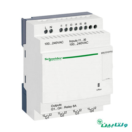
SR2D101FU
- Simple ladder programming, adapted for non-specialists
- Discovery package, coming with Zelio Soft programming software: the simplest way to learn and use this relay
- Built-in EEPROM flash memory for data backup up to 10 years: easy-to-recover after a power shortage or incident
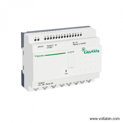
SR2D201BD
- Simple ladder programming, adapted for non-specialists
- Discovery package, coming with Zelio Soft programming software: the simplest way to learn and use this relay
- Built-in EEPROM flash memory for data backup up to 10 years: easy-to-recover after a power shortage or incident
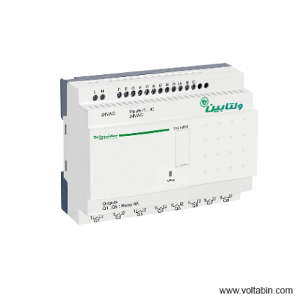
SR2E201B
- Extreme compactness
- Simple ladder programming, adapted for non-specialists
- Discovery package, coming with Zelio Soft programming software: the simplest way to learn and use this relay
- Built-in EEPROM flash memory for data backup up to 10 years: easy-to-recover after a power shortage or incident
- Flexible

SR2SFT01
-
Range of product Zelio Logic Product or component type Programming software Product compatibility Zelio Logic compact and modular smart relay Software designation Zelio Soft 2 multi-language Software version V5.4.0 Operating system Windows 7 32/64 bit (V5.4.0 and older software versions)multilingual
Windows 8.1 32/64 bit (V5.4.0 and older software versions)multilingual
Windows 10 32/64 bit (V5.4.0 and older software versions)multilingualFormat CD Software function FDB language program editor
Ladder language program editorNet weight 0.2 kg
SR3B261B
- Simple ladder programming, adapted for non-specialists
- Discovery package, coming with Zelio Soft programming software: the simplest way to learn and use this relay
- Built-in EEPROM flash memory for data backup up to 10 years: easy-to-recover after a power shortage or incident
- More I/O than SR2 model, for larger applications
-
Range of product Zelio Logic Product or component type Modular smart relay local display With Number or control scheme lines 0…500 with FBD programming
0…240 with ladder programmingCycle time 6…90 ms Backup time 10 years at 25 °C Clock drift 12 min/year at 0…55 °C
6 s/month at 25 °CChecks Program memory on each power up [Us] rated supply voltage 24 V Supply voltage limits 20.4…28.8 V Supply frequency 50/60 Hz Maximum supply current 280 mA (without extension)
415 mA (with extensions)Power consumption in VA 10 VA with extensions
7.5 VA without extensionIsolation voltage 1780 V Protection type Against inversion of terminals (control instructions not executed) Discrete input number 16 Discrete input voltage 24 V AC Discrete input current 4.4 mA Discrete input frequency 47…53 Hz
57…63 HzVoltage state 1 guaranteed >= 14 V for discrete input Voltage state 0 guaranteed <= 5 V for discrete input Current state 1 guaranteed >= 2 mA (discrete input) Current state 0 guaranteed <= 0.5 mA (discrete input) Input impedance 4.6 kOhm for discrete input Number of outputs 10 relay Output voltage limits 5…30 V DC (relay output)
24…250 V ACContacts type and composition NO for relay output Output thermal current 5 A for 2 outputs for relay output
8 A for 8 outputs for relay outputElectrical durability AC-12: 500000 cycles at 230 V, 1.5 A for relay output conforming to EN/IEC 60947-5-1
AC-15: 500000 cycles at 230 V, 0.9 A for relay output conforming to EN/IEC 60947-5-1
DC-12: 500000 cycles at 24 V, 1.5 A for relay output conforming to EN/IEC 60947-5-1
DC-13: 500000 cycles at 24 V, 0.6 A for relay output conforming to EN/IEC 60947-5-1Switching capacity in mA >= 10 mA at 12 V (relay output) Operating rate in Hz 0.1 Hz (at Ie) for relay output
10 Hz (no load) for relay outputMechanical durability 10000000 cycles for relay output [Uimp] rated impulse withstand voltage 4 kV conforming to EN/IEC 60947-1 and EN/IEC 60664-1 Clock With Response time 50 ms with ladder programming (from state 0 to state 1) for discrete input
50 ms with ladder programming (from state 1 to state 0) for discrete input
50…255 ms with FBD programming (from state 0 to state 1) for discrete input
50…255 ms with FBD programming (from state 1 to state 0) for discrete input
10 ms (from state 0 to state 1) for relay output
5 ms (from state 1 to state 0) for relay outputConnections – terminals Screw terminals, 1 x 0.2…1 x 2.5 mm² (AWG 25…AWG 14) semi-solid
Screw terminals, 1 x 0.2…1 x 2.5 mm² (AWG 25…AWG 14) solid
Screw terminals, 1 x 0.25…1 x 2.5 mm² (AWG 24…AWG 14) flexible with cable end
Screw terminals, 2 x 0.2…2 x 1.5 mm² (AWG 24…AWG 16) solid
Screw terminals, 2 x 0.25…2 x 0.75 mm² (AWG 24…AWG 18) flexible with cable endTightening torque 0.5 N.m Overvoltage category III conforming to EN/IEC 60664-1 Net weight 0.4 kg Immunity to microbreaks 10 ms repeated 20 times Product certifications GOST
GL
UL
CSA
C-TickStandards EN/IEC 61000-4-5
EN/IEC 61000-4-11
EN/IEC 61000-4-2 level 3
EN/IEC 61000-4-6 level 3
EN/IEC 60068-2-6 Fc
EN/IEC 60068-2-27 Ea
EN/IEC 61000-4-4 level 3
EN/IEC 61000-4-3
EN/IEC 61000-4-12IP degree of protection IP20 (terminal block) conforming to IEC 60529
IP40 (front panel) conforming to IEC 60529Environmental characteristic EMC directive conforming to EN/IEC 61000-6-2
EMC directive conforming to EN/IEC 61000-6-3
EMC directive conforming to EN/IEC 61000-6-4
EMC directive conforming to EN/IEC 61131-2 zone B
Low voltage directive conforming to EN/IEC 61131-2Disturbance radiated/conducted Class B conforming to EN 55022-11 group 1 Pollution degree 2 conforming to EN/IEC 61131-2 Ambient air temperature for operation -20…40 °C in non-ventilated enclosure conforming to IEC 60068-2-1 and IEC 60068-2-2
-20…55 °C conforming to IEC 60068-2-1 and IEC 60068-2-2Ambient air temperature for storage -40…70 °C Operating altitude 2000 m Maximum altitude transport 3048 m Relative humidity 95 % without condensation or dripping water Unit Type of Package 1 PCE Number of Units in Package 1 1 Package 1 Height 6.8 cm Package 1 Width 10.0 cm Package 1 Length 13.5 cm Package 1 Weight 383.0 g Unit Type of Package 2 S03 Number of Units in Package 2 20 Package 2 Height 30.0 cm Package 2 Width 30.0 cm Package 2 Length 40.0 cm Package 2 Weight 8.204 kg
SR3B261BD
-
Range of Product Zelio Logic Product or Component Type Modular smart relay local display With Number or control scheme lines 0…500 FBD
0…240 ladderCycle time 6…90 ms Backup time 10 years 77 °F (25 °C) Clock drift 12 min/year 32…131 °F (0…55 °C)
6 s/month 77 °F (25 °C)Checks Program memory on each power up [Us] rated supply voltage 24 V Supply voltage limits 19.2…30 V Maximum supply current 190 mA without extension)
300 mA with extensions)Power dissipation in W 10 W with extensions
6 W without extensionReverse polarity protection With Discrete input number 16 EN/IEC 61131-2 type 1 Discrete input type Resistive Discrete input voltage 24 V DC Discrete input current 4 mA Counting frequency 1 kHz discrete input Voltage state 1 guaranteed >= 15 V I1…IA and IH…IR discrete input circuit
>= 15 V IB…IG used as discrete input circuitVoltage state 0 guaranteed <= 5 V I1…IA and IH…IR discrete input circuit
<= 5 V IB…IG used as discrete input circuitCurrent state 1 guaranteed >= 1.2 mA IB…IG used as discrete input circuit)
>= 2.2 mA I1…IA and IH…IR discrete input circuit)Current state 0 guaranteed <= 0.5 mA IB…IG used as discrete input circuit)
<= 0.75 mA I1…IA and IH…IR discrete input circuit)Input compatibility 3-wire proximity sensors PNP discrete input Analogue input number 6 Analogue Input Type Common mode Analogue input range 0…10 V
0…24 VTemperature probe type NTC 10k 77 °F (25 °C)
NTC 1000k 77 °F (25 °C)
KTY81 210/220/221/222/250
Pt 500Maximum permissible voltage 30 V analogue input circuit Analogue input resolution 8 bits LSB value 39 mV analogue input circuit Conversion time Smart relay cycle time analogue input circuit Conversion error +/- 5 % 77 °F (25 °C) analogue input circuit
+/- 6.2 % 131 °F (55 °C) analogue input circuitRepeat accuracy +/- 2 % 131 °F (55 °C) analogue input circuit Operating distance 10 m between stations, with screened cable (sensor not isolated) analogue input circuit Input impedance 12 kOhm IB…IG used as analogue input circuit
12 kOhm IB…IG used as discrete input circuit
7.4 kOhm I1…IA and IH…IR discrete input circuitNumber of Outputs 10 relay Output voltage limits 24…250 V AC relay output)
5…30 V DC relay output)Contacts type and composition NO relay output Output thermal current 5 A for 2 outputs relay output
8 A for 8 outputs relay outputElectrical durability AC-12 500000 cycles 230 V, 1.5 A relay output EN/IEC 60947-5-1
AC-15 500000 cycles 230 V, 0.9 A relay output EN/IEC 60947-5-1
DC-12 500000 cycles 24 V, 1.5 A relay output EN/IEC 60947-5-1
DC-13 500000 cycles 24 V, 0.6 A relay output EN/IEC 60947-5-1Switching capacity in mA >= 10 mA 12 V relay output) Operating rate in Hz 0.1 Hz at Ie)relay output
10 Hz no load)relay outputMechanical durability 10000000 cycles relay output [Uimp] rated impulse withstand voltage 4 kV EN/IEC 60947-1 and EN/IEC 60664-1 Clock With Response time 10 ms from state 0 to state 1)relay output
5 ms from state 1 to state 0)relay outputConnections – terminals Screw terminals, 1 x 0.2…1 x 2.5 mm² AWG 25…AWG 14) semi-solid
Screw terminals, 1 x 0.2…1 x 2.5 mm² AWG 25…AWG 14) solid
Screw terminals, 1 x 0.25…1 x 2.5 mm² AWG 24…AWG 14) flexible with cable end
Screw terminals, 2 x 0.2…2 x 1.5 mm² AWG 24…AWG 16) solid
Screw terminals, 2 x 0.25…2 x 0.75 mm² AWG 24…AWG 18) flexible with cable endTightening torque 4.43 lbf.in (0.5 N.m) Overvoltage category III EN/IEC 60664-1 Net Weight 0.88 lb(US) (0.4 kg) Immunity to microbreaks 1 ms Product Certifications GL
C-tick
CSA
UL
GOSTStandards EN/IEC 61000-4-2 level 3
EN/IEC 61000-4-5
EN/IEC 61000-4-6 level 3
EN/IEC 61000-4-11
EN/IEC 61000-4-3
EN/IEC 60068-2-27 Ea
EN/IEC 61000-4-12
EN/IEC 60068-2-6 Fc
EN/IEC 61000-4-4 level 3IP degree of protection IP20 IEC 60529 terminal block)
IP40 IEC 60529 front panel)Environmental characteristic EMC directive EN/IEC 61000-6-2
EMC directive EN/IEC 61000-6-3
EMC directive EN/IEC 61000-6-4
EMC directive EN/IEC 61131-2 zone B
Low voltage directive EN/IEC 61131-2Disturbance radiated/conducted Class B EN 55022-11 group 1 Pollution degree 2 EN/IEC 61131-2 Ambient air temperature for operation -4…104 °F (-20…40 °C) in non-ventilated enclosure IEC 60068-2-1 and IEC 60068-2-2
-4…131 °F (-20…55 °C) IEC 60068-2-1 and IEC 60068-2-2Ambient Air Temperature for Storage -40…158 °F (-40…70 °C) Operating altitude 6561.68 ft (2000 m) Maximum altitude transport 10000.00 ft (3048 m) Relative Humidity 95 % without condensation or dripping water Unit Type of Package 1 PCE Number of Units in Package 1 1 Package 1 Height 2.68 in (6.8 cm) Package 1 Width 3.94 in (10.0 cm) Package 1 Length 5.31 in (13.5 cm) Package 1 Weight 13.44 oz (381.0 g) Unit Type of Package 2 S03 Number of Units in Package 2 20 Package 2 Height 11.81 in (30.0 cm) Package 2 Width 11.81 in (30.0 cm) Package 2 Length 15.75 in (40.0 cm) Package 2 Weight 17.84 lb(US) (8.094 kg)
SR3B261FU
- Simple ladder programming, adapted for non-specialists
- Discovery package, coming with Zelio Soft programming software: the simplest way to learn and use this relay
- Built-in EEPROM flash memory for data backup up to 10 years: easy-to-recover after a power shortage or incident
- More I/O than SR2 model, for larger applications
-
Range of product Zelio Logic Product or component type Modular smart relay local display With Number or control scheme lines 0…500 with FBD programming
0…240 with ladder programmingCycle time 6…90 ms Backup time 10 years at 25 °C Clock drift 12 min/year at 0…55 °C
6 s/month at 25 °CChecks Program memory on each power up [Us] rated supply voltage 100…240 V Supply voltage limits 85…264 V Supply frequency 50/60 Hz Maximum supply current 100 mA at 100 V (without extension)
50 mA at 240 V (without extension)
60 mA at 240 V (with extensions)
80 mA at 100 V (with extensions)Power consumption in VA 12 VA without extension
17 VA with extensionsIsolation voltage 1780 V Protection type Against inversion of terminals (control instructions not executed) Discrete input number 16 Discrete input voltage 100…240 V AC Discrete input current 0.6 mA Discrete input frequency 47…53 Hz
57…63 HzVoltage state 1 guaranteed >= 79 V for discrete input Voltage state 0 guaranteed <= 40 V for discrete input Current state 1 guaranteed >= 0.17 mA (discrete input) Current state 0 guaranteed <= 0.5 mA (discrete input) Input impedance 350 kOhm for discrete input Number of outputs 10 relay Output voltage limits 5…30 V DC (relay output)
24…250 V ACContacts type and composition NO for relay output Output thermal current 5 A for 2 outputs for relay output
8 A for 8 outputs for relay outputElectrical durability AC-12: 500000 cycles at 230 V, 1.5 A for relay output conforming to EN/IEC 60947-5-1
AC-15: 500000 cycles at 230 V, 0.9 A for relay output conforming to EN/IEC 60947-5-1
DC-12: 500000 cycles at 24 V, 1.5 A for relay output conforming to EN/IEC 60947-5-1
DC-13: 500000 cycles at 24 V, 0.6 A for relay output conforming to EN/IEC 60947-5-1Switching capacity in mA >= 10 mA at 12 V (relay output) Operating rate in Hz 0.1 Hz (at Ie) for relay output
10 Hz (no load) for relay outputMechanical durability 10000000 cycles for relay output [Uimp] rated impulse withstand voltage 4 kV conforming to EN/IEC 60947-1 and EN/IEC 60664-1 Clock With Response time 50 ms with ladder programming (from state 0 to state 1) for discrete input
50 ms with ladder programming (from state 1 to state 0) for discrete input
50…255 ms with FBD programming (from state 0 to state 1) for discrete input
50…255 ms with FBD programming (from state 1 to state 0) for discrete input
10 ms (from state 0 to state 1) for relay output
5 ms (from state 1 to state 0) for relay outputConnections – terminals Screw terminals, 1 x 0.2…1 x 2.5 mm² (AWG 25…AWG 14) semi-solid
Screw terminals, 1 x 0.2…1 x 2.5 mm² (AWG 25…AWG 14) solid
Screw terminals, 1 x 0.25…1 x 2.5 mm² (AWG 24…AWG 14) flexible with cable end
Screw terminals, 2 x 0.2…2 x 1.5 mm² (AWG 24…AWG 16) solid
Screw terminals, 2 x 0.25…2 x 0.75 mm² (AWG 24…AWG 18) flexible with cable endTightening torque 0.5 N.m Overvoltage category III conforming to EN/IEC 60664-1 Net weight 0.4 kg Immunity to microbreaks 10 ms Product certifications GOST
GL
CSA
UL
C-TickStandards EN/IEC 61000-4-12
EN/IEC 60068-2-27 Ea
EN/IEC 60068-2-6 Fc
EN/IEC 61000-4-6 level 3
EN/IEC 61000-4-5
EN/IEC 61000-4-11
EN/IEC 61000-4-3
EN/IEC 61000-4-2 level 3
EN/IEC 61000-4-4 level 3IP degree of protection IP20 (terminal block) conforming to IEC 60529
IP40 (front panel) conforming to IEC 60529Environmental characteristic EMC directive conforming to EN/IEC 61000-6-2
EMC directive conforming to EN/IEC 61000-6-3
EMC directive conforming to EN/IEC 61000-6-4
EMC directive conforming to EN/IEC 61131-2 zone B
Low voltage directive conforming to EN/IEC 61131-2Disturbance radiated/conducted Class B conforming to EN 55022-11 group 1 Pollution degree 2 conforming to EN/IEC 61131-2 Ambient air temperature for operation -20…40 °C in non-ventilated enclosure conforming to IEC 60068-2-1 and IEC 60068-2-2
-20…55 °C conforming to IEC 60068-2-1 and IEC 60068-2-2Ambient air temperature for storage -40…70 °C Operating altitude 2000 m Maximum altitude transport 3048 m Relative humidity 95 % without condensation or dripping water Unit Type of Package 1 PCE Number of Units in Package 1 1 Package 1 Height 6.8 cm Package 1 Width 13.5 cm Package 1 Length 10.0 cm Package 1 Weight 390.0 g Unit Type of Package 2 S03 Number of Units in Package 2 20 Package 2 Height 30.0 cm Package 2 Width 30.0 cm Package 2 Length 40.0 cm Package 2 Weight 8.302 kg
SR3B261JD
- Simple ladder programming, adapted for non-specialists
- Discovery package, coming with Zelio Soft programming software: the simplest way to learn and use this relay
- Built-in EEPROM flash memory for data backup up to 10 years: easy-to-recover after a power shortage or incident
- More I/O than SR2 model, for larger applications
-
Range of product Zelio Logic Product or component type Modular smart relay local display With Number or control scheme lines 0…500 with FBD programming
0…240 with ladder programmingCycle time 6…90 ms Backup time 10 years at 25 °C Clock drift 12 min/year at 0…55 °C
6 s/month at 25 °CChecks Program memory on each power up [Us] rated supply voltage 12 V Supply voltage limits 10.4…14.4 V Maximum supply current 250 mA (without extension)
400 mA (with extensions)Power dissipation in W 3 W without extension
5 W with extensionsReverse polarity protection With Discrete input number 16 conforming to EN/IEC 61131-2 type 1 Discrete input type Resistive Discrete input voltage 12 V DC Discrete input current 4 mA Counting frequency 1 kHz for discrete input Voltage state 1 guaranteed >= 7 V for IB…IG used as discrete input circuit
>= 5.6 V for I1…IA and IH…IR discrete input circuitVoltage state 0 guaranteed <= 3 V for IB…IG used as discrete input circuit
<= 2.4 V for I1…IA and IH…IR discrete input circuitCurrent state 1 guaranteed >= 2 mA (I1…IA and IH…IR discrete input circuit)
>= 0.5 mA (IB…IG used as discrete input circuit)Current state 0 guaranteed <= 0.2 mA (IB…IG used as discrete input circuit)
<= 0.9 mA (I1…IA and IH…IR discrete input circuit)Input compatibility 3-wire proximity sensors PNP for discrete input Analogue input number 6 Analogue input type Common mode Analogue input range 0…12 V
0…10 VMaximum permissible voltage 14.4 V for analogue input circuit Analogue input resolution 8 bits at maximum voltage LSB value 39 mV for analogue input circuit Conversion time Smart relay cycle time for analogue input circuit Conversion error +/- 5 % at 25 °C for analogue input circuit
+/- 6.2 % at 55 °C for analogue input circuitRepeat accuracy +/- 2 % at 55 °C for analogue input circuit Operating distance 10 m between stations, with screened cable (sensor not isolated) for analogue input circuit Input impedance 14 kOhm for IB…IG used as analogue input circuit
14 kOhm for IB…IG used as discrete input circuit
2.7 kOhm for I1…IA and IH…IR discrete input circuitNumber of outputs 10 relay Output voltage limits 24…250 V AC (relay output)
5…30 V DC (relay output)Contacts type and composition NO for relay output Output thermal current 5 A for 2 outputs for relay output
8 A for 8 outputs for relay outputElectrical durability AC-12: 500000 cycles at 230 V, 1.5 A for relay output conforming to EN/IEC 60947-5-1
AC-15: 500000 cycles at 230 V, 0.9 A for relay output conforming to EN/IEC 60947-5-1
DC-12: 500000 cycles at 24 V, 1.5 A for relay output conforming to EN/IEC 60947-5-1
DC-13: 500000 cycles at 24 V, 0.6 A for relay output conforming to EN/IEC 60947-5-1Switching capacity in mA >= 10 mA at 12 V (relay output) Operating rate in Hz 0.1 Hz (at Ie) for relay output
10 Hz (no load) for relay outputMechanical durability 10000000 cycles for relay output [Uimp] rated impulse withstand voltage 4 kV conforming to EN/IEC 60947-1 and EN/IEC 60664-1 Clock With Response time 10 ms (from state 0 to state 1) for relay output
5 ms (from state 1 to state 0) for relay outputConnections – terminals Screw terminals, 1 x 0.2…1 x 2.5 mm² (AWG 25…AWG 14) semi-solid
Screw terminals, 1 x 0.2…1 x 2.5 mm² (AWG 25…AWG 14) solid
Screw terminals, 1 x 0.25…1 x 2.5 mm² (AWG 24…AWG 14) flexible with cable end
Screw terminals, 2 x 0.2…2 x 1.5 mm² (AWG 24…AWG 16) solid
Screw terminals, 2 x 0.25…2 x 0.75 mm² (AWG 24…AWG 18) flexible with cable endTightening torque 0.5 N.m Overvoltage category III conforming to EN/IEC 60664-1 Net weight 0.4 kg Immunity to microbreaks 1 ms repeated 20 times Product certifications C-Tick
UL
CSA
GL
GOSTStandards EN/IEC 60068-2-6 Fc
EN/IEC 61000-4-12
EN/IEC 61000-4-3
EN/IEC 61000-4-6 level 3
EN/IEC 61000-4-5
EN/IEC 61000-4-11
EN/IEC 61000-4-2 level 3
EN/IEC 60068-2-27 Ea
EN/IEC 61000-4-4 level 3IP degree of protection IP20 (terminal block) conforming to IEC 60529
IP40 (front panel) conforming to IEC 60529Environmental characteristic EMC directive conforming to EN/IEC 61000-6-2
EMC directive conforming to EN/IEC 61000-6-3
EMC directive conforming to EN/IEC 61000-6-4
EMC directive conforming to EN/IEC 61131-2 zone B
Low voltage directive conforming to EN/IEC 61131-2Disturbance radiated/conducted Class B conforming to EN 55022-11 group 1 Pollution degree 2 conforming to EN/IEC 61131-2 Ambient air temperature for operation -20…40 °C in non-ventilated enclosure conforming to IEC 60068-2-1 and IEC 60068-2-2
-20…55 °C conforming to IEC 60068-2-1 and IEC 60068-2-2Ambient air temperature for storage -40…70 °C Operating altitude 2000 m Maximum altitude transport 3048 m Relative humidity 95 % without condensation or dripping water Unit Type of Package 1 PCE Number of Units in Package 1 1 Package 1 Height 6.8 cm Package 1 Width 10 cm Package 1 Length 13.3 cm Package 1 Weight 383 g Unit Type of Package 2 S03 Number of Units in Package 2 20 Package 2 Height 30 cm Package 2 Width 30 cm Package 2 Length 40 cm Package 2 Weight 8.056 kg
SR3B262BD
- Simple ladder programming, adapted for non-specialists
- Discovery package, coming with Zelio Soft programming software: the simplest way to learn and use this relay
- Built-in EEPROM flash memory for data backup up to 10 years: easy-to-recover after a power shortage or incident
- More I/O than SR2 model, for larger applications
-
Range of product Zelio Logic Product or component type Modular smart relay local display With Number or control scheme lines 0…500 with FBD programming
0…240 with ladder programmingCycle time 6…90 ms Backup time 10 years at 25 °C Clock drift 12 min/year at 0…55 °C
6 s/month at 25 °CChecks Program memory on each power up [Us] rated supply voltage 24 V Supply voltage limits 19.2…30 V Maximum supply current 180 mA (with extensions)
70 mA (without extension)Power dissipation in W 10 W with extensions
5 W without extensionReverse polarity protection With Discrete input number 16 conforming to EN/IEC 61131-2 type 1 Discrete input type Resistive Discrete input voltage 24 V DC Discrete input current 4 mA Counting frequency 1 kHz for discrete input Voltage state 1 guaranteed >= 15 V for I1…IA and IH…IR discrete input circuit
>= 15 V for IB…IG used as discrete input circuitVoltage state 0 guaranteed <= 5 V for I1…IA and IH…IR discrete input circuit
<= 5 V for IB…IG used as discrete input circuitCurrent state 1 guaranteed >= 1.2 mA (IB…IG used as discrete input circuit)
>= 2.2 mA (I1…IA and IH…IR discrete input circuit)Current state 0 guaranteed <= 0.5 mA (IB…IG used as discrete input circuit)
<= 0.75 mA (I1…IA and IH…IR discrete input circuit)Input compatibility 3-wire proximity sensors PNP for discrete input Analogue input number 6 Analogue input type Common mode Analogue input range 0…24 V
0…10 VTemperature probe type NTC 10k at 25 °C
NTC 1000k at 25 °C
KTY81 210/220/221/222/250
Pt 500Maximum permissible voltage 30 V for analogue input circuit Analogue input resolution 8 bits LSB value 39 mV for analogue input circuit Conversion time Smart relay cycle time for analogue input circuit Conversion error +/- 5 % at 25 °C for analogue input circuit
+/- 6.2 % at 55 °C for analogue input circuitRepeat accuracy +/- 2 % at 55 °C for analogue input circuit Operating distance 10 m between stations, with screened cable (sensor not isolated) for analogue input circuit Input impedance 12 kOhm for IB…IG used as analogue input circuit
12 kOhm for IB…IG used as discrete input circuit
7.4 kOhm for I1…IA and IH…IR discrete input circuitNumber of outputs 10 transistor Output voltage 24 V transistor output Output voltage limits 19.2…30 V DC (transistor output) [Uimp] rated impulse withstand voltage 4 kV conforming to EN/IEC 60947-1 and EN/IEC 60664-1 Load current 0.5…0.625 A transistor output [Ures] residual voltage 2 V at state 1 transistor output Overload protection With overload protection for transistor output Short-circuit protection With transistor output Overvoltage protection With overvoltage protection for transistor output Clock With Response time <= 1 ms (from state 0 to state 1) for transistor output
<= 1 ms (from state 1 to state 0) for transistor outputConnections – terminals Screw terminals, 1 x 0.2…1 x 2.5 mm² (AWG 25…AWG 14) semi-solid
Screw terminals, 1 x 0.2…1 x 2.5 mm² (AWG 25…AWG 14) solid
Screw terminals, 1 x 0.25…1 x 2.5 mm² (AWG 24…AWG 14) flexible with cable end
Screw terminals, 2 x 0.2…2 x 1.5 mm² (AWG 24…AWG 16) solid
Screw terminals, 2 x 0.25…2 x 0.75 mm² (AWG 24…AWG 18) flexible with cable endTightening torque 0.5 N.m Overvoltage category III conforming to EN/IEC 60664-1 Net weight 0.3 kg Immunity to microbreaks 1 ms Product certifications C-Tick
GOST
UL
CSA
GLStandards EN/IEC 60068-2-27 Ea
EN/IEC 61000-4-5
EN/IEC 61000-4-11
EN/IEC 61000-4-6 level 3
EN/IEC 61000-4-12
EN/IEC 61000-4-4 level 3
EN/IEC 61000-4-3
EN/IEC 61000-4-2 level 3
EN/IEC 60068-2-6 FcIP degree of protection IP20 (terminal block) conforming to IEC 60529
IP40 (front panel) conforming to IEC 60529Environmental characteristic EMC directive conforming to EN/IEC 61000-6-2
EMC directive conforming to EN/IEC 61000-6-3
EMC directive conforming to EN/IEC 61000-6-4
EMC directive conforming to EN/IEC 61131-2 zone B
Low voltage directive conforming to EN/IEC 61131-2Disturbance radiated/conducted Class B conforming to EN 55022-11 group 1 Pollution degree 2 conforming to EN/IEC 61131-2 Ambient air temperature for operation -20…40 °C in non-ventilated enclosure conforming to IEC 60068-2-1 and IEC 60068-2-2
-20…55 °C conforming to IEC 60068-2-1 and IEC 60068-2-2Ambient air temperature for storage -40…70 °C Operating altitude 2000 m Maximum altitude transport 3048 m Relative humidity 95 % without condensation or dripping water Unit Type of Package 1 PCE Number of Units in Package 1 1 Package 1 Height 6.8 cm Package 1 Width 10.0 cm Package 1 Length 13.5 cm Package 1 Weight 298.0 g Unit Type of Package 2 S03 Number of Units in Package 2 20 Package 2 Height 30.0 cm Package 2 Width 30.0 cm Package 2 Length 40.0 cm Package 2 Weight 6.586 kg

SR3PACKBD
- Reverse polarity protection
- Simple ladder programming, adapted for non-specialists
- Discovery package, coming with Zelio Soft programming software: the simplest way to learn and use this relay
- Built-in EEPROM flash memory for data backup up to 10 years: easy-to-recover after a power shortage or incident
- CSA, C-Tick, GOST, GL and UL certified
-
Range of product Zelio Logic Product or component type Modular discovery packs Discrete input number 6 conforming to EN/IEC 61131-2 type 1 Number of outputs 4 relay kit composition SR3B101BD
Cable PC SR2USB01 for connection to PCInput/output number 10 local display With Number or control scheme lines 120 with ladder programming
0…200 with FBD programmingCycle time 6…90 ms Backup time 10 years at 25 °C Clock drift 12 min/year at 0…55 °C
6 s/month at 25 °CChecks Program memory on each power up [Us] rated supply voltage 24 V Supply voltage limits 19.2…30 V Maximum supply current 100 mA (with extensions)
100 mA (without extension)Power dissipation in W 3 W without extension
8 W with extensionsReverse polarity protection With Discrete input type Resistive Discrete input voltage 24 V DC Discrete input current 4 mA Counting frequency 1 kHz for discrete input Voltage state 1 guaranteed >= 15 V for I1…IA and IH…IR discrete input circuit
>= 15 V for IB…IG used as discrete input circuitVoltage state 0 guaranteed <= 5 V for I1…IA and IH…IR discrete input circuit
<= 5 V for IB…IG used as discrete input circuit
<= 5 VCurrent state 1 guaranteed >= 1.2 mA (IB…IG used as discrete input circuit)
>= 2.2 mA (I1…IA and IH…IR discrete input circuit)Current state 0 guaranteed <= 0.5 mA (IB…IG used as discrete input circuit)
<= 0.75 mA (I1…IA and IH…IR discrete input circuit)Input compatibility 3-wire proximity sensors PNP for discrete input Analogue input number 4 Analogue input type Common mode Analogue input range 0…24 V
0…10 VTemperature probe type NTC 10k at 25 °C
NTC 1000k at 25 °C
KTY81 210/220/221/222/250
Pt 500Maximum permissible voltage 30 V for analogue input circuit Analogue input resolution 8 bits LSB value 39 mV for analogue input circuit Conversion time Smart relay cycle time for analogue input circuit Conversion error +/- 5 % at 25 °C for analogue input circuit
+/- 6.2 % at 55 °C for analogue input circuitRepeat accuracy +/- 2 % at 55 °C for analogue input circuit Operating distance 10 m between stations, with screened cable (sensor not isolated) for analogue input circuit Input impedance 12 kOhm for IB…IG used as analogue input circuit
12 kOhm for IB…IG used as discrete input circuit
7.4 kOhm for I1…IA and IH…IR discrete input circuitOutput voltage limits 24…250 V AC (relay output)
5…30 V DC (relay output)Contacts type and composition NO for relay output Output thermal current 8 A for all 4 outputs for relay output Electrical durability AC-12: 500000 cycles at 230 V, 1.5 A for relay output conforming to EN/IEC 60947-5-1
AC-15: 500000 cycles at 230 V, 0.9 A for relay output conforming to EN/IEC 60947-5-1
DC-12: 500000 cycles at 24 V, 1.5 A for relay output conforming to EN/IEC 60947-5-1
DC-13: 500000 cycles at 24 V, 0.6 A for relay output conforming to EN/IEC 60947-5-1Switching capacity in mA >= 10 mA at 12 V (relay output) Operating rate in Hz 0.1 Hz (at Ie) for relay output
10 Hz (no load) for relay outputMechanical durability 10000000 cycles for relay output [Uimp] rated impulse withstand voltage 4 kV conforming to EN/IEC 60947-1 and EN/IEC 60664-1 Clock With Response time 10 ms (from state 0 to state 1) for relay output
5 ms (from state 1 to state 0) for relay outputConnections – terminals Screw terminals, 1 x 0.2…1 x 2.5 mm² (AWG 25…AWG 14) semi-solid
Screw terminals, 1 x 0.2…1 x 2.5 mm² (AWG 25…AWG 14) solid
Screw terminals, 1 x 0.25…1 x 2.5 mm² (AWG 24…AWG 14) flexible with cable end
Screw terminals, 2 x 0.2…2 x 1.5 mm² (AWG 24…AWG 16) solid
Screw terminals, 2 x 0.25…2 x 0.75 mm² (AWG 24…AWG 18) flexible with cable endTightening torque 0.5 N.m Overvoltage category III conforming to EN/IEC 60664-1 Net weight 0.7 kg Immunity to microbreaks 1 ms Product certifications GL
UL
CSA
GOST
C-TickStandards EN/IEC 60068-2-27 Ea
EN/IEC 60068-2-6 Fc
EN/IEC 61000-4-3
EN/IEC 61000-4-6 level 3
EN/IEC 61000-4-11
EN/IEC 61000-4-5
EN/IEC 61000-4-2 level 3
EN/IEC 61000-4-12
EN/IEC 61000-4-4 level 3IP degree of protection IP20 (terminal block) conforming to IEC 60529
IP40 (front panel) conforming to IEC 60529Environmental characteristic EMC directive conforming to EN/IEC 61000-6-2
EMC directive conforming to EN/IEC 61000-6-3
EMC directive conforming to EN/IEC 61000-6-4
EMC directive conforming to EN/IEC 61131-2 zone B
Low voltage directive conforming to EN/IEC 61131-2Disturbance radiated/conducted Class B conforming to EN 55022-11 group 1 Pollution degree 2 conforming to EN/IEC 61131-2 Ambient air temperature for operation -20…40 °C in non-ventilated enclosure conforming to IEC 60068-2-1 and IEC 60068-2-2
-20…55 °C conforming to IEC 60068-2-1 and IEC 60068-2-2Ambient air temperature for storage -40…70 °C Operating altitude 2000 m Maximum altitude transport 3048 m Relative humidity 95 % without condensation or dripping water Unit Type of Package 1 PCE Number of Units in Package 1 1 Package 1 Height 6.2 cm Package 1 Width 15.5 cm Package 1 Length 23.3 cm Package 1 Weight 390 g Unit Type of Package 2 S03 Number of Units in Package 2 10 Package 2 Height 30 cm Package 2 Width 30 cm Package 2 Length 40 cm Package 2 Weight 4.409 kg