
همه محصولات
- اشنایدر الکتریک589 محصول
- overcurrent-relay-schneider-electric0 محصول
- اتوماسیون صنعتی (PLC)229 محصول
- الکتریکال262 محصول
- درایو – اینورتر52 محصول
- سافت استارتر46 محصول
- زیمنس3,624 محصول
- همه محصولات3,619 محصول
فیلترها
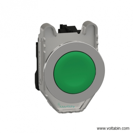
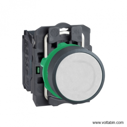
XB4BW31B5
Range of Product Harmony XB4 Product or Component Type Illuminated push-button device short name XB4 bezel material Chromium plated metal Fixing collar material Zamak Mounting diameter 0.87 in (22 mm) Sale per indivisible quantity 1 Head type Standard Shape of signaling unit head Round Type of operator Spring return Operator profile White flush Operator additional information With plain lens Contacts type and composition 1 NO + 1 NC contact operation Slow-break Connections – terminals Screw clamp terminals, <= 2 x 1.5 mm² with cable end EN/IEC 60947-1
Screw clamp terminals, 1 x 0.22…2 x 2.5 mm² without cable end EN/IEC 60947-1Light source Universal LED Bulb base Integral LED [Us] rated supply voltage 24 V AC/DC 50/60 Hz Height 1.85 in (47 mm) Width 1.18 in (30 mm) Depth 2.24 in (57 mm) Terminals description ISO n°1 (13-14)NO
(21-22)NCNet Weight 0.21 lb(US) (0.097 kg) Resistance to high pressure washer 1015.26 psi (7000000 Pa) 131 °F (55 °C) 0.1 m contacts usage Standard contacts Positive opening With EN/IEC 60947-5-1 appendix K Operating travel 0.06 in (1.5 mm) NC changing electrical state)
0.10 in (2.6 mm) NO changing electrical state)
0.17 in (4.3 mm) total travel)Operating force 3.5 N NC changing electrical state
3.8 NMechanical durability 10000000 cycles Tightening torque 7.08…10.62 lbf.in (0.8…1.2 N.m) EN 60947-1 Shape of screw head Cross Philips no 1
Cross pozidriv No 1
Slotted flat Ø 4 mm
Slotted flat Ø 5.5 mmContacts material Silver alloy (Ag/Ni) Short-circuit protection 10 A cartridge fuse gG EN/IEC 60947-5-1 [Ith] conventional free air thermal current 10 A EN/IEC 60947-5-1 [Ui] rated insulation voltage 600 V 3)EN/IEC 60947-1 [Uimp] rated impulse withstand voltage 6 kV EN/IEC 60947-1 [Ie] rated operational current 3 A 240 V, AC-15, A600 EN/IEC 60947-5-1
6 A 120 V, AC-15, A600 EN/IEC 60947-5-1
0.1 A 600 V, DC-13, Q600 EN/IEC 60947-5-1
0.27 A 250 V, DC-13, Q600 EN/IEC 60947-5-1
0.55 A 125 V, DC-13, Q600 EN/IEC 60947-5-1
1.2 A 600 V, AC-15, A600 EN/IEC 60947-5-1Electrical durability 1000000 cycles, AC-15, 2 A 230 V 3600 cyc/h 0.5 EN/IEC 60947-5-1 appendix C
1000000 cycles, AC-15, 3 A 120 V 3600 cyc/h 0.5 EN/IEC 60947-5-1 appendix C
1000000 cycles, AC-15, 4 A 24 V 3600 cyc/h 0.5 EN/IEC 60947-5-1 appendix C
1000000 cycles, DC-13, 0.2 A 110 V 3600 cyc/h 0.5 EN/IEC 60947-5-1 appendix C
1000000 cycles, DC-13, 0.5 A 24 V 3600 cyc/h 0.5 EN/IEC 60947-5-1 appendix CElectrical reliability Λ < 10exp(-6) 5 V 1 mA in clean environment EN/IEC 60947-5-4
Λ < 10exp(-8) 17 V 5 mA in clean environment EN/IEC 60947-5-4Signalling type Steady Current Consumption 18 mA Service life 100000 h at rated voltage and 25 °C Surge withstand 1 kV IEC 61000-4-5 Supply voltage limits 19.2…30 V DC
21.6…26.4 V ACDevice presentation Complete product Protective treatment TH Ambient Air Temperature for Storage -40…158 °F (-40…70 °C) Ambient air temperature for operation -40…158 °F (-40…70 °C) Electrical shock protection class Class I IEC 60536 IP degree of protection IP66 IEC 60529
IP67
IP69
IP69KNEMA degree of protection NEMA 13
NEMA 4XIK degree of protection IK06 IEC 50102 Standards EN/IEC 60947-5-5
CSA C22.2 No 14
EN/IEC 60947-5-4
EN/IEC 60947-5-1
JIS C8201-5-1
UL 508
EN/IEC 60947-1
JIS C8201-1Product Certifications DNV
CSA
UL Listed
LROS (Lloyds register of shipping)
GL
BVVibration resistance 5 gn 2…500 Hz)IEC 60068-2-6 Shock resistance 30 gn 18 ms) half sine wave acceleration IEC 60068-2-27
50 gn 11 ms) half sine wave acceleration IEC 60068-2-27Resistance to fast transients 2 kV IEC 61000-4-4 Resistance to electromagnetic fields 9.14 V/m (10 V/m) IEC 61000-4-3 Resistance to electrostatic discharge 6 kV on contact (on metal parts) IEC 61000-4-2
8 kV in free air (in insulating parts) IEC 61000-4-2Electromagnetic emission Class B IEC 55011 Unit Type of Package 1 PCE Number of Units in Package 1 1 Package 1 Height 1.38 in (3.5 cm) Package 1 Width 2.17 in (5.5 cm) Package 1 Length 3.35 in (8.5 cm) Package 1 Weight 3.40 oz (96.25 g) Unit Type of Package 2 S03 Number of Units in Package 2 100 Package 2 Height 11.81 in (30.0 cm) Package 2 Width 11.81 in (30.0 cm) Package 2 Length 15.75 in (40.0 cm) Package 2 Weight 22.22 lb(US) (10.079 kg) Unit Type of Package 3 P06 Number of Units in Package 3 800 Package 3 Height 29.53 in (75.0 cm) Package 3 Width 31.50 in (80.0 cm) Package 3 Length 23.62 in (60.0 cm) Package 3 Weight 195.40 lb(US) (88.632 kg)
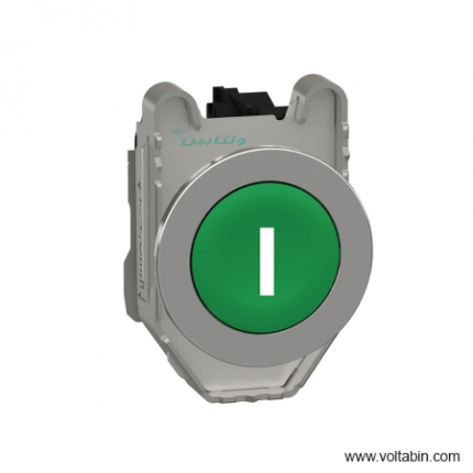
XB4BW31M5
Range of product Harmony XB4 Product or component type Illuminated push-button device short name XB4 bezel material Chromium plated metal Fixing collar material Zamak Mounting diameter 22 mm Sale per indivisible quantity 1 Head type Standard Shape of signaling unit head Round Type of operator Spring return Operator profile White flush Operator additional information With plain lens contacts type and composition 1 NO + 1 NC contact operation Slow-break Connections – terminals Screw clamp terminals, <= 2 x 1.5 mm² with cable end conforming to EN/IEC 60947-1
Screw clamp terminals, 1 x 0.22…2 x 2.5 mm² without cable end conforming to EN/IEC 60947-1Light source Universal LED bulb base Integral LED [Us] rated supply voltage 230…240 V AC at 50/60 Hz Height 47 mm Width 30 mm Depth 57 mm Terminals description ISO n°1 (21-22)NC
(13-14)NONet weight 0.097 kg Resistance to high pressure washer 7000000 Pa at 55 °C, distance : 0.1 m contacts usage Standard contacts Positive opening With conforming to EN/IEC 60947-5-1 appendix K Operating travel 1.5 mm (NC changing electrical state)
2.6 mm (NO changing electrical state)
4.3 mm (total travel)Operating force 3.5 N NC changing electrical state
3.8 NMechanical durability 10000000 cycles Tightening torque 0.8…1.2 N.m conforming to EN 60947-1 Shape of screw head Cross compatible with Philips no 1 screwdriver
Cross compatible with pozidriv No 1 screwdriver
Slotted compatible with flat Ø 4 mm screwdriver
Slotted compatible with flat Ø 5.5 mm screwdrivercontacts material Silver alloy (Ag/Ni) Short-circuit protection 10 A cartridge fuse type gG conforming to EN/IEC 60947-5-1 [Ith] conventional free air thermal current 10 A conforming to EN/IEC 60947-5-1 [Ui] rated insulation voltage 600 V (pollution degree 3) conforming to EN/IEC 60947-1 [Uimp] rated impulse withstand voltage 6 kV conforming to EN/IEC 60947-1 [Ie] rated operational current 3 A at 240 V, AC-15, A600 conforming to EN/IEC 60947-5-1
6 A at 120 V, AC-15, A600 conforming to EN/IEC 60947-5-1
0.1 A at 600 V, DC-13, Q600 conforming to EN/IEC 60947-5-1
0.27 A at 250 V, DC-13, Q600 conforming to EN/IEC 60947-5-1
0.55 A at 125 V, DC-13, Q600 conforming to EN/IEC 60947-5-1
1.2 A at 600 V, AC-15, A600 conforming to EN/IEC 60947-5-1Electrical durability 1000000 cycles, AC-15, 2 A at 230 V, operating rate <3600 cyc/h, load factor: 0.5 conforming to EN/IEC 60947-5-1 appendix C
1000000 cycles, AC-15, 3 A at 120 V, operating rate <3600 cyc/h, load factor: 0.5 conforming to EN/IEC 60947-5-1 appendix C
1000000 cycles, AC-15, 4 A at 24 V, operating rate <3600 cyc/h, load factor: 0.5 conforming to EN/IEC 60947-5-1 appendix C
1000000 cycles, DC-13, 0.2 A at 110 V, operating rate <3600 cyc/h, load factor: 0.5 conforming to EN/IEC 60947-5-1 appendix C
1000000 cycles, DC-13, 0.5 A at 24 V, operating rate <3600 cyc/h, load factor: 0.5 conforming to EN/IEC 60947-5-1 appendix CElectrical reliability Λ < 10exp(-6) at 5 V and 1 mA in clean environment conforming to EN/IEC 60947-5-4
Λ < 10exp(-8) at 17 V and 5 mA in clean environment conforming to EN/IEC 60947-5-4Signalling type Steady current consumption 14 mA Service life 100000 h at rated voltage and 25 °C Surge withstand 1 kV conforming to IEC 61000-4-5 Supply voltage limits 195…264 V AC device presentation Complete product Protective treatment TH Ambient air temperature for storage -40…70 °C Ambient air temperature for operation -40…70 °C Electrical shock protection class Class I conforming to IEC 60536 IP degree of protection IP66 conforming to IEC 60529
IP67
IP69
IP69KNEMA degree of protection NEMA 13
NEMA 4XIK degree of protection IK06 conforming to IEC 50102 Standards EN/IEC 60947-5-5
EN/IEC 60947-5-4
UL 508
CSA C22.2 No 14
JIS C8201-5-1
EN/IEC 60947-5-1
EN/IEC 60947-1
JIS C8201-1product certifications BV
UL listed
DNV
LROS (Lloyds register of shipping)
GL
CSAVibration resistance 5 gn (f= 2…500 Hz) conforming to IEC 60068-2-6 Shock resistance 30 gn (duration = 18 ms) for half sine wave acceleration conforming to IEC 60068-2-27
50 gn (duration = 11 ms) for half sine wave acceleration conforming to IEC 60068-2-27Resistance to fast transients 2 kV conforming to IEC 61000-4-4 Resistance to electromagnetic fields 10 V/m conforming to IEC 61000-4-3 Resistance to electrostatic discharge 6 kV on contact (on metal parts) conforming to IEC 61000-4-2
8 kV in free air (in insulating parts) conforming to IEC 61000-4-2Electromagnetic emission Class B conforming to IEC 55011 Unit Type of Package 1 PCE Number of Units in Package 1 1 Package 1 Height 8.8 cm Package 1 Width 3.4 cm Package 1 Length 5.4 cm Package 1 Weight 96.0 g Unit Type of Package 2 S02 Number of Units in Package 2 50 Package 2 Height 15 cm Package 2 Width 30 cm Package 2 Length 40 cm Package 2 Weight 5.114 kg
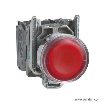
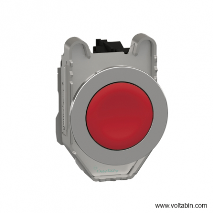
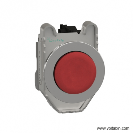
XB4BW3465
Range of product Harmony XB4 Product or component type Illuminated push-button device short name XB4 Bezel material Chromium plated metal Fixing collar material Zamak Mounting diameter 22 mm Sale per indivisible quantity 1 Head type Standard Shape of signaling unit head Round Type of operator Spring return Operator profile Red flush Operator additional information With plain lens Contacts type and composition 1 NO + 1 NC Contact operation Slow-break Connections – terminals Screw clamp terminals, <= 2 x 1.5 mm² with cable end conforming to EN/IEC 60947-1
Screw clamp terminals, 1 x 0.22…2 x 2.5 mm² without cable end conforming to EN/IEC 60947-1Light source Bulb not included Bulb base BA 9s Light block supply Direct <2.4 W [Us] rated supply voltage <= 250 V Height 47 mm Width 30 mm Depth 57 mm Terminals description ISO n°1 (21-22)NC
(13-14)NOProduct weight 0.097 kg Resistance to high pressure washer 7000000 Pa at 55 °C, distance : 0.1 m Contacts usage Standard contacts Positive opening With conforming to EN/IEC 60947-5-1 appendix K Operating travel 1.5 mm (NC changing electrical state)
2.6 mm (NO changing electrical state)
4.3 mm (total travel)Operating force 3.5 N NC changing electrical state
3.8 NMechanical durability 10000000 cycles Tightening torque 0.8…1.2 N.m conforming to EN 60947-1 Shape of screw head Cross compatible with Philips no 1 screwdriver
Cross compatible with pozidriv No 1 screwdriver
Slotted compatible with flat Ø 4 mm screwdriver
Slotted compatible with flat Ø 5.5 mm screwdriverContacts material Silver alloy (Ag/Ni) Short-circuit protection 10 A cartridge fuse type gG conforming to EN/IEC 60947-5-1 [Ith] conventional free air thermal current 10 A conforming to EN/IEC 60947-5-1 [Ui] rated insulation voltage 600 V (pollution degree 3) conforming to EN/IEC 60947-1 [Uimp] rated impulse withstand voltage 6 kV conforming to EN/IEC 60947-1 [Ie] rated operational current 3 A at 240 V, AC-15, A600 conforming to EN/IEC 60947-5-1
6 A at 120 V, AC-15, A600 conforming to EN/IEC 60947-5-1
0.1 A at 600 V, DC-13, Q600 conforming to EN/IEC 60947-5-1
0.27 A at 250 V, DC-13, Q600 conforming to EN/IEC 60947-5-1
0.55 A at 125 V, DC-13, Q600 conforming to EN/IEC 60947-5-1
1.2 A at 600 V, AC-15, A600 conforming to EN/IEC 60947-5-1Electrical durability 1000000 cycles, AC-15, 2 A at 230 V, operating rate <3600 cyc/h, load factor: 0.5 conforming to EN/IEC 60947-5-1 appendix C
1000000 cycles, AC-15, 3 A at 120 V, operating rate <3600 cyc/h, load factor: 0.5 conforming to EN/IEC 60947-5-1 appendix C
1000000 cycles, AC-15, 4 A at 24 V, operating rate <3600 cyc/h, load factor: 0.5 conforming to EN/IEC 60947-5-1 appendix C
1000000 cycles, DC-13, 0.2 A at 110 V, operating rate <3600 cyc/h, load factor: 0.5 conforming to EN/IEC 60947-5-1 appendix C
1000000 cycles, DC-13, 0.5 A at 24 V, operating rate <3600 cyc/h, load factor: 0.5 conforming to EN/IEC 60947-5-1 appendix CElectrical reliability Λ < 10exp(-6) at 5 V and 1 mA in clean environment conforming to EN/IEC 60947-5-4
Λ < 10exp(-8) at 17 V and 5 mA in clean environment conforming to EN/IEC 60947-5-4Signalling type Steady Device presentation Complete product Protective treatment TH Ambient air temperature for storage -40…70 °C Ambient air temperature for operation -40…55 °C Electrical shock protection class Class I conforming to IEC 60536 IP degree of protection IP66 conforming to IEC 60529
IP67
IP69
IP69KNEMA degree of protection NEMA 13
NEMA 4XIK degree of protection IK06 conforming to IEC 50102 Standards EN/IEC 60947-5-5
CSA C22.2 No 14
EN/IEC 60947-5-1
JIS C8201-5-1
EN/IEC 60947-5-4
UL 508
EN/IEC 60947-1
JIS C8201-1Product certifications UL listed
GL
CSA
LROS (Lloyds register of shipping)
DNV
BVVibration resistance 5 gn (f= 2…500 Hz) conforming to IEC 60068-2-6 Shock resistance 30 gn (duration = 18 ms) for half sine wave acceleration conforming to IEC 60068-2-27
50 gn (duration = 11 ms) for half sine wave acceleration conforming to IEC 60068-2-27Unit Type of Package 1 PCE Number of Units in Package 1 1 Package 1 Height 3.4 cm Package 1 Width 5.0 cm Package 1 Length 8.6 cm Package 1 Weight 96.0 g Unit Type of Package 2 S02 Number of Units in Package 2 55 Package 2 Height 15.0 cm Package 2 Width 30.0 cm Package 2 Length 40.0 cm Package 2 Weight 5.595 kg

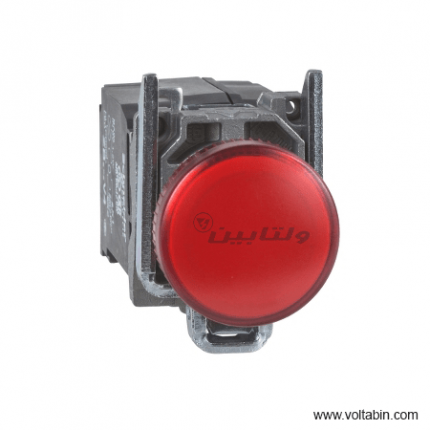
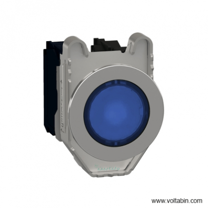
XB4BW34B5
Range of Product Harmony XB4 Product or Component Type Illuminated push-button device short name XB4 Bezel material Chromium plated metal Fixing collar material Zamak Mounting diameter 0.87 in (22 mm) Sale per indivisible quantity 1 Head type Standard Shape of signaling unit head Round Type of operator Spring return Operator profile Red flush Operator additional information With plain lens Contacts type and composition 1 NO + 1 NC Contact operation Slow-break Connections – terminals Screw clamp terminals, <= 2 x 1.5 mm² with cable end EN/IEC 60947-1
Screw clamp terminals, 1 x 0.22…2 x 2.5 mm² without cable end EN/IEC 60947-1Light source Universal LED Bulb base Integral LED [Us] rated supply voltage 24 V AC/DC 50/60 Hz Height 1.85 in (47 mm) Width 1.18 in (30 mm) Depth 2.24 in (57 mm) Terminals description ISO n°1 (13-14)NO
(21-22)NCProduct Weight 0.21 lb(US) (0.097 kg) Resistance to high pressure washer 1015.26 psi (7000000 Pa) 131 °F (55 °C) 0.1 m Contacts usage Standard contacts Positive opening With EN/IEC 60947-5-1 appendix K Operating travel 0.06 in (1.5 mm) NC changing electrical state)
0.10 in (2.6 mm) NO changing electrical state)
0.17 in (4.3 mm) total travel)Operating force 3.5 N NC changing electrical state
3.8 NMechanical durability 10000000 cycles Tightening torque 7.08…10.62 lbf.in (0.8…1.2 N.m) EN 60947-1 Shape of screw head Cross Philips no 1
Cross pozidriv No 1
Slotted flat Ø 4 mm
Slotted flat Ø 5.5 mmContacts material Silver alloy (Ag/Ni) Short-circuit protection 10 A cartridge fuse gG EN/IEC 60947-5-1 [Ith] conventional free air thermal current 10 A EN/IEC 60947-5-1 [Ui] rated insulation voltage 600 V 3)EN/IEC 60947-1 [Uimp] rated impulse withstand voltage 6 kV EN/IEC 60947-1 [Ie] rated operational current 3 A 240 V, AC-15, A600 EN/IEC 60947-5-1
6 A 120 V, AC-15, A600 EN/IEC 60947-5-1
0.1 A 600 V, DC-13, Q600 EN/IEC 60947-5-1
0.27 A 250 V, DC-13, Q600 EN/IEC 60947-5-1
0.55 A 125 V, DC-13, Q600 EN/IEC 60947-5-1
1.2 A 600 V, AC-15, A600 EN/IEC 60947-5-1Electrical durability 1000000 cycles, AC-15, 2 A 230 V 3600 cyc/h 0.5 EN/IEC 60947-5-1 appendix C
1000000 cycles, AC-15, 3 A 120 V 3600 cyc/h 0.5 EN/IEC 60947-5-1 appendix C
1000000 cycles, AC-15, 4 A 24 V 3600 cyc/h 0.5 EN/IEC 60947-5-1 appendix C
1000000 cycles, DC-13, 0.2 A 110 V 3600 cyc/h 0.5 EN/IEC 60947-5-1 appendix C
1000000 cycles, DC-13, 0.5 A 24 V 3600 cyc/h 0.5 EN/IEC 60947-5-1 appendix CElectrical reliability Λ < 10exp(-6) 5 V 1 mA in clean environment EN/IEC 60947-5-4
Λ < 10exp(-8) 17 V 5 mA in clean environment EN/IEC 60947-5-4Signalling type Steady Current Consumption 18 mA Service life 100000 h at rated voltage and 25 °C Surge withstand 1 kV IEC 61000-4-5 Supply voltage limits 19.2…30 V DC
21.6…26.4 V ACDevice presentation Complete product Protective treatment TH Ambient Air Temperature for Storage -40…158 °F (-40…70 °C) Ambient Air Temperature for Operation -40…158 °F (-40…70 °C) Electrical shock protection class Class I IEC 60536 IP degree of protection IP66 IEC 60529
IP67
IP69
IP69KNEMA degree of protection NEMA 13
NEMA 4XIK degree of protection IK06 IEC 50102 Standards EN/IEC 60947-5-5
UL 508
EN/IEC 60947-5-1
CSA C22.2 No 14
EN/IEC 60947-1
EN/IEC 60947-5-4
JIS C8201-5-1
JIS C8201-1Product Certifications BV
UL Listed
DNV
CSA
LROS (Lloyds register of shipping)
GLVibration resistance 5 gn 2…500 Hz)IEC 60068-2-6 Shock resistance 30 gn 18 ms) half sine wave acceleration IEC 60068-2-27
50 gn 11 ms) half sine wave acceleration IEC 60068-2-27Resistance to fast transients 2 kV IEC 61000-4-4 Resistance to electromagnetic fields 9.14 V/m (10 V/m) IEC 61000-4-3 Resistance to electrostatic discharge 6 kV on contact (on metal parts) IEC 61000-4-2
8 kV in free air (in insulating parts) IEC 61000-4-2Electromagnetic emission Class B IEC 55011 Unit Type of Package 1 PCE Number of Units in Package 1 1 Package 1 Height 1.38 in (3.500 cm) Package 1 Width 2.17 in (5.500 cm) Package 1 Length 3.54 in (9.000 cm) Package 1 Weight 3.40 oz (96.300 g) Unit Type of Package 2 S03 Number of Units in Package 2 150 Package 2 Height 11.81 in (30.000 cm) Package 2 Width 11.81 in (30.000 cm) Package 2 Length 15.75 in (40.000 cm) Package 2 Weight 32.78 lb(US) (14.867 kg) Unit Type of Package 3 P06 Number of Units in Package 3 1200 Package 3 Height 29.53 in (75.000 cm) Package 3 Width 31.50 in (80.000 cm) Package 3 Length 23.62 in (60.000 cm) Package 3 Weight 279.84 lb(US) (126.932 kg)
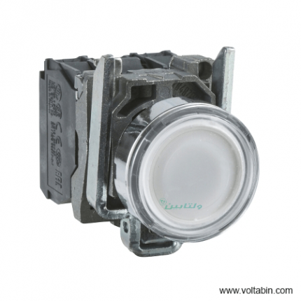
XB4FA11
Range of Product Harmony XB4 Product or Component Type Push-button device short name XB4F Product Compatibility ZBYF…
ZBZF32
ZBZF33Bezel material Chromium plated metal Fixing collar material Zamak Mounting diameter 1.20 in (30.5 mm) Sale per indivisible quantity 1 Shape of signaling unit head Round Type of operator Spring return Operator profile White flush, unmarked Head type Built-in-flush Contacts type and composition 1 NO Contact operation Slow-break Connections – terminals Screw clamp terminals, <= 2 x 1.5 mm² with cable end EN/IEC 60947-1
Screw clamp terminals, 1 x 0.22…2 x 2.5 mm² without cable end EN/IEC 60947-1Height 1.85 in (47 mm) Width 1.44 in (36.6 mm) Depth 2.17 in (55 mm) Terminals description ISO n°1 (13-14)NO Product Weight 0.26 lb(US) (0.116 kg) Resistance to high pressure washer 1015.26 psi (7000000 Pa) 131 °F (55 °C) 0.1 m Device mounting Built-in Fixing mode By screws Contacts usage Standard contacts Positive opening Without Operating travel 0.10 in (2.6 mm) NO changing electrical state)
0.17 in (4.3 mm) total travel)Operating force 3.8 N NO changing electrical state Mechanical durability 10000000 cycles Tightening torque 7.08…10.62 lbf.in (0.8…1.2 N.m) EN 60947-1 Shape of screw head Cross Philips no 1
Cross pozidriv No 1
Slotted flat Ø 4 mm
Slotted flat Ø 5.5 mmContacts material Silver alloy (Ag/Ni) Short-circuit protection 10 A cartridge fuse gG EN/IEC 60947-5-1 [Ith] conventional free air thermal current 10 A EN/IEC 60947-5-1 [Ui] rated insulation voltage 600 V 3)EN/IEC 60947-1 [Uimp] rated impulse withstand voltage 6 kV EN/IEC 60947-1 [Ie] rated operational current 3 A 240 V, AC-15, A600 EN/IEC 60947-5-1
6 A 120 V, AC-15, A600 EN/IEC 60947-5-1
0.1 A 600 V, DC-13, Q600 EN/IEC 60947-5-1
0.27 A 250 V, DC-13, Q600 EN/IEC 60947-5-1
0.55 A 125 V, DC-13, Q600 EN/IEC 60947-5-1
1.2 A 600 V, AC-15, A600 EN/IEC 60947-5-1Electrical durability 1000000 cycles, AC-15, 2 A 230 V 3600 cyc/h 0.5 EN/IEC 60947-5-1 appendix C
1000000 cycles, AC-15, 3 A 120 V 3600 cyc/h 0.5 EN/IEC 60947-5-1 appendix C
1000000 cycles, AC-15, 4 A 24 V 3600 cyc/h 0.5 EN/IEC 60947-5-1 appendix C
1000000 cycles, DC-13, 0.2 A 110 V 3600 cyc/h 0.5 EN/IEC 60947-5-1 appendix C
1000000 cycles, DC-13, 0.5 A 24 V 3600 cyc/h 0.5 EN/IEC 60947-5-1 appendix CElectrical reliability Λ < 10exp(-6) 5 V 1 mA in clean environment EN/IEC 60947-5-4
Λ < 10exp(-8) 17 V 5 mA in clean environment EN/IEC 60947-5-4Device presentation Complete product Protective treatment TH Ambient Air Temperature for Storage -40…158 °F (-40…70 °C) Ambient Air Temperature for Operation -40…158 °F (-40…70 °C) Overvoltage category Class I IEC 60536 IP degree of protection IP66 IEC 60529
IP67
IP69
IP69KNEMA degree of protection NEMA 13
NEMA 4XIK degree of protection IK06 IEC 50102 Standards CSA C22.2 No 14
EN/IEC 60947-5-1
EN/IEC 60947-5-4
UL 508
EN/IEC 60947-1
JIS C8201-5-1
JIS C8201-1Product Certifications UL Listed
CSAVibration resistance 5 gn 2…500 Hz)IEC 60068-2-6 Shock resistance 30 gn 18 ms) half sine wave acceleration IEC 60068-2-27
50 gn 11 ms) half sine wave acceleration IEC 60068-2-27Unit Type of Package 1 PCE Number of Units in Package 1 1 Package 1 Height 1.69 in (4.3 cm) Package 1 Width 2.05 in (5.2 cm) Package 1 Length 3.39 in (8.6 cm) Package 1 Weight 3.95 oz (112.0 g)
XB4FA31
range of product
Easy Altivar 610
product or component type
Variable speed drive
product specific application
Fan, pump, compressor, conveyor
device short name
ATV610
variant
Standard version
product destination
Asynchronous motors
mounting mode
Cabinet mount
EMC filter
Integrated conforming to EN/IEC 61800-3 category C3 with 50 m
IP degree of protection
IP20
type of cooling
Forced convection
supply frequency
50…60 Hz +/-5 %
network number of phases
3 phases
[Us] rated supply voltage
380…460 V – 15…10 %
motor power kW
110 kW for normal duty
90 kW for heavy duty
motor power hp
150 hp for normal duty
125 hp for heavy duty
line current
201 A at 380 V (normal duty)
175.7 A at 460 V (normal duty)
170 A at 380 V (heavy duty)
149.1 A at 460 V (heavy duty)
prospective line Isc
50 kA
apparent power
140.0 kVA at 460 V (normal duty)
118.8 kVA at 460 V (heavy duty)
continuous output current
211 A at 2.5 kHz for normal duty
173 A at 2.5 kHz for heavy duty
maximum transient current
232 A during 60 s (normal duty)
260 A during 60 s (heavy duty)
asynchronous motor control profile
Variable torque standard
Optimized torque mode
Constant torque standard
output frequency
0.0001…0.5 kHz
nominal switching frequency
2.5 kHz
switching frequency
1…8 kHz adjustable
number of preset speeds
16 preset speeds
communication port protocol
Modbus serial
option card
Slot A: communication card, Profibus DP V1
Slot A: digital or analog I/O extension card
Slot A: relay output card
output voltage
<= power supply voltage
motor slip compensation
Can be suppressed
Adjustable
Not available in permanent magnet motor law
Automatic whatever the load
acceleration and deceleration ramps
Linear adjustable separately from 0.01 to 9000 s
S, U or customized
braking to standstill
By DC injection
protection type
Thermal protection: motor
Motor phase break: motor
Thermal protection: drive
Overheating: drive
Overcurrent between output phases and earth: drive
Overload of output voltage: drive
Short-circuit protection: drive
Motor phase break: drive
Overvoltages on the DC bus: drive
Line supply overvoltage: drive
Line supply undervoltage: drive
Line supply phase loss: drive
Overspeed: drive
Break on the control circuit: drive
frequency resolution
Display unit: 0.1 Hz
Analog input: 0.012/50 Hz
electrical connection
Control, screw terminal: 0.5…1.5 mm²
Line side, screw terminal: 2 x 50…3 x 120 mm²
Motor, screw terminal: 3 x 50…3 x 120 mm²
connector type
1 RJ45 (on the remote graphic terminal) for Modbus serial
physical interface
2-wire RS 485 for Modbus serial
transmission frame
RTU for Modbus serial
transmission rate
4.8, 9.6, 19.2, 38.4 kbit/s for Modbus serial
type of polarization
No impedance for Modbus serial
number of addresses
1…247 for Modbus serial
method of access
Slave
supply
External supply for digital inputs: 24 V DC (19…30 V), <1.25 mA, protection type: overload and short-circuit protection
Internal supply for reference potentiometer (1 to 10 kOhm): 10.5 V DC +/- 5 %, <10 mA, protection type: overload and short-circuit protection
local signalling
2 LEDs for local diagnostic
1 LED (yellow) for embedded communication status
2 LEDs (dual colour) for communication module status
1 LED (red) for presence of voltage
width
320 mm
height
852 mm
1159 mm with IP21 conformity kit
depth
390 mm
net weight
82 kg
analogue input number
3
analogue input type
AI1, AI2, AI3 software-configurable voltage: 0…10 V DC, impedance: 30 kOhm, resolution 12 bits
AI1, AI2, AI3 software-configurable current: 0…20 mA, impedance: 250 Ohm, resolution 12 bits
AI2, AI3 software-configurable temperature probe or water level sensor
discrete input number
6
discrete input type
DI1…DI6 programmable as logic input, 24 V DC (<= 30 V), impedance: 3.5 kOhm
DI5, DI6 programmable as pulse input: 0…30 kHz, 24 V DC (<= 30 V)
input compatibility
DI1…DI6: logic input level 1 PLC conforming to EN/IEC 61131-2
DI5, DI6: pulse input level 1 PLC conforming to IEC 65A-68
discrete input logic
Positive logic (source): DI1…DI6 configurable logic input, < 5 V (state 0), > 11 V (state 1)
Negative logic (sink): DI1…DI6 configurable logic input, > 16 V (state 0), < 10 V (state 1)
Positive logic (source): DI5, DI6 configurable pulse input, < 0.6 V (state 0), > 2.5 V (state 1)
analogue output number
2
analogue output type
Software-configurable current AQ1, AQ2: 0…20 mA, resolution 10 bits
Software-configurable voltage AQ1, AQ2: 0…10 V DC impedance 470 Ohm, resolution 10 bits
sampling duration
5 ms +/- 0.1 ms (AI1, AI2, AI3) – analog input
2 ms +/- 0.5 ms (DI1…DI6)configurable – discrete input
5 ms +/- 1 ms (DI5, DI6)configurable – pulse input
10 ms +/- 1 ms (AQ1, AQ2) – analog output
accuracy
+/- 0.6 % AI1, AI2, AI3 for a temperature variation 60 °C analog input
+/- 1 % AQ1, AQ2 for a temperature variation 60 °C analog output
linearity error
AI1, AI2, AI3: +/- 0.15 % of maximum value for analog input
AQ1, AQ2: +/- 0.2 % for analog output
relay output number
3
relay output type
Configurable relay logic R1: fault relay NO/NC electrical durability 100000 cycles
Configurable relay logic R2: sequence relay NO electrical durability 100000 cycles
Configurable relay logic R3: sequence relay NO electrical durability 100000 cycles
refresh time
Relay output (R1, R2, R3): 5 ms (+/- 0.5 ms)
minimum switching current
Relay output R1, R2, R3: 5 mA at 24 V DC
maximum switching current
Relay output R1, R2, R3 on resistive load, cos phi = 1: 3 A at 250 V AC
Relay output R1, R2, R3 on resistive load, cos phi = 1: 3 A at 30 V DC
Relay output R1, R2, R3 on inductive load, cos phi = 0.4 and L/R = 7 ms: 2 A at 250 V AC
Relay output R1, R2, R3 on inductive load, cos phi = 0.4 and L/R = 7 ms: 2 A at 30 V DC
isolation
Between power and control terminals
insulation resistance
> 1 MOhm 500 V DC for 1 minute to earth
noise level
76 dB conforming to 86/188/EEC
power dissipation in W
2026 W(forced convection) at 380 V, switching frequency 2.5 kHz
operating position
Vertical +/- 10 degree
electromagnetic compatibility
Electrostatic discharge immunity test level 3 conforming to IEC 61000-4-2
Radiated radio-frequency electromagnetic field immunity test level 3 conforming to IEC 61000-4-3
Electrical fast transient/burst immunity test level 4 conforming to IEC 61000-4-4
1.2/50 µs – 8/20 µs surge immunity test level 3 conforming to IEC 61000-4-5
Conducted radio-frequency immunity test level 3 conforming to IEC 61000-4-6
pollution degree
2 conforming to EN/IEC 61800-5-1
vibration resistance
1.5 mm peak to peak (f= 2…13 Hz) conforming to IEC 60068-2-6
1 gn (f= 13…200 Hz) conforming to IEC 60068-2-6
shock resistance
6 gn for 11 ms conforming to IEC 60068-2-27
relative humidity
5…95 % without condensation conforming to IEC 60068-2-3
ambient air temperature for operation
-15…45 °C (without derating)
45…60 °C (with derating factor)
operating altitude
<= 1000 m without derating
1000…4800 m with current derating 1 % per 100 m
environmental characteristic
Chemical pollution resistance class 3C3 conforming to EN/IEC 60721-3-3
Dust pollution resistance class 3S3 conforming to EN/IEC 60721-3-3
standards
EN/IEC 61800-3
Environment 2 category C3 EN/IEC 61800-3
EN/IEC 61800-5-1
IEC 60721-3
marking
CE
Unit Type of Package 1
PCE
Number of Units in Package 1
1
Package 1 Weight
96.344 kg
Package 1 Height
47 cm
Package 1 width
67 cm
Package 1 Length
103 cm
XB4FA3311
range of product
Easy Altivar 610
product or component type
Variable speed drive
product specific application
Fan, pump, compressor, conveyor
device short name
ATV610
variant
Standard version
product destination
Asynchronous motors
mounting mode
Cabinet mount
EMC filter
Integrated conforming to EN/IEC 61800-3 category C3 with 50 m
IP degree of protection
IP20
type of cooling
Forced convection
supply frequency
50…60 Hz +/-5 %
network number of phases
3 phases
[Us] rated supply voltage
380…460 V – 15…10 %
motor power kW
110 kW for normal duty
90 kW for heavy duty
motor power hp
150 hp for normal duty
125 hp for heavy duty
line current
201 A at 380 V (normal duty)
175.7 A at 460 V (normal duty)
170 A at 380 V (heavy duty)
149.1 A at 460 V (heavy duty)
prospective line Isc
50 kA
apparent power
140.0 kVA at 460 V (normal duty)
118.8 kVA at 460 V (heavy duty)
continuous output current
211 A at 2.5 kHz for normal duty
173 A at 2.5 kHz for heavy duty
maximum transient current
232 A during 60 s (normal duty)
260 A during 60 s (heavy duty)
asynchronous motor control profile
Variable torque standard
Optimized torque mode
Constant torque standard
output frequency
0.0001…0.5 kHz
nominal switching frequency
2.5 kHz
switching frequency
1…8 kHz adjustable
number of preset speeds
16 preset speeds
communication port protocol
Modbus serial
option card
Slot A: communication card, Profibus DP V1
Slot A: digital or analog I/O extension card
Slot A: relay output card
output voltage
<= power supply voltage
motor slip compensation
Can be suppressed
Adjustable
Not available in permanent magnet motor law
Automatic whatever the load
acceleration and deceleration ramps
Linear adjustable separately from 0.01 to 9000 s
S, U or customized
braking to standstill
By DC injection
protection type
Thermal protection: motor
Motor phase break: motor
Thermal protection: drive
Overheating: drive
Overcurrent between output phases and earth: drive
Overload of output voltage: drive
Short-circuit protection: drive
Motor phase break: drive
Overvoltages on the DC bus: drive
Line supply overvoltage: drive
Line supply undervoltage: drive
Line supply phase loss: drive
Overspeed: drive
Break on the control circuit: drive
frequency resolution
Display unit: 0.1 Hz
Analog input: 0.012/50 Hz
electrical connection
Control, screw terminal: 0.5…1.5 mm²
Line side, screw terminal: 2 x 50…3 x 120 mm²
Motor, screw terminal: 3 x 50…3 x 120 mm²
connector type
1 RJ45 (on the remote graphic terminal) for Modbus serial
physical interface
2-wire RS 485 for Modbus serial
transmission frame
RTU for Modbus serial
transmission rate
4.8, 9.6, 19.2, 38.4 kbit/s for Modbus serial
type of polarization
No impedance for Modbus serial
number of addresses
1…247 for Modbus serial
method of access
Slave
supply
External supply for digital inputs: 24 V DC (19…30 V), <1.25 mA, protection type: overload and short-circuit protection
Internal supply for reference potentiometer (1 to 10 kOhm): 10.5 V DC +/- 5 %, <10 mA, protection type: overload and short-circuit protection
local signalling
2 LEDs for local diagnostic
1 LED (yellow) for embedded communication status
2 LEDs (dual colour) for communication module status
1 LED (red) for presence of voltage
width
320 mm
height
852 mm
1159 mm with IP21 conformity kit
depth
390 mm
net weight
82 kg
analogue input number
3
analogue input type
AI1, AI2, AI3 software-configurable voltage: 0…10 V DC, impedance: 30 kOhm, resolution 12 bits
AI1, AI2, AI3 software-configurable current: 0…20 mA, impedance: 250 Ohm, resolution 12 bits
AI2, AI3 software-configurable temperature probe or water level sensor
discrete input number
6
discrete input type
DI1…DI6 programmable as logic input, 24 V DC (<= 30 V), impedance: 3.5 kOhm
DI5, DI6 programmable as pulse input: 0…30 kHz, 24 V DC (<= 30 V)
input compatibility
DI1…DI6: logic input level 1 PLC conforming to EN/IEC 61131-2
DI5, DI6: pulse input level 1 PLC conforming to IEC 65A-68
discrete input logic
Positive logic (source): DI1…DI6 configurable logic input, < 5 V (state 0), > 11 V (state 1)
Negative logic (sink): DI1…DI6 configurable logic input, > 16 V (state 0), < 10 V (state 1)
Positive logic (source): DI5, DI6 configurable pulse input, < 0.6 V (state 0), > 2.5 V (state 1)
analogue output number
2
analogue output type
Software-configurable current AQ1, AQ2: 0…20 mA, resolution 10 bits
Software-configurable voltage AQ1, AQ2: 0…10 V DC impedance 470 Ohm, resolution 10 bits
sampling duration
5 ms +/- 0.1 ms (AI1, AI2, AI3) – analog input
2 ms +/- 0.5 ms (DI1…DI6)configurable – discrete input
5 ms +/- 1 ms (DI5, DI6)configurable – pulse input
10 ms +/- 1 ms (AQ1, AQ2) – analog output
accuracy
+/- 0.6 % AI1, AI2, AI3 for a temperature variation 60 °C analog input
+/- 1 % AQ1, AQ2 for a temperature variation 60 °C analog output
linearity error
AI1, AI2, AI3: +/- 0.15 % of maximum value for analog input
AQ1, AQ2: +/- 0.2 % for analog output
relay output number
3
relay output type
Configurable relay logic R1: fault relay NO/NC electrical durability 100000 cycles
Configurable relay logic R2: sequence relay NO electrical durability 100000 cycles
Configurable relay logic R3: sequence relay NO electrical durability 100000 cycles
refresh time
Relay output (R1, R2, R3): 5 ms (+/- 0.5 ms)
minimum switching current
Relay output R1, R2, R3: 5 mA at 24 V DC
maximum switching current
Relay output R1, R2, R3 on resistive load, cos phi = 1: 3 A at 250 V AC
Relay output R1, R2, R3 on resistive load, cos phi = 1: 3 A at 30 V DC
Relay output R1, R2, R3 on inductive load, cos phi = 0.4 and L/R = 7 ms: 2 A at 250 V AC
Relay output R1, R2, R3 on inductive load, cos phi = 0.4 and L/R = 7 ms: 2 A at 30 V DC
isolation
Between power and control terminals
insulation resistance
> 1 MOhm 500 V DC for 1 minute to earth
noise level
76 dB conforming to 86/188/EEC
power dissipation in W
2026 W(forced convection) at 380 V, switching frequency 2.5 kHz
operating position
Vertical +/- 10 degree
electromagnetic compatibility
Electrostatic discharge immunity test level 3 conforming to IEC 61000-4-2
Radiated radio-frequency electromagnetic field immunity test level 3 conforming to IEC 61000-4-3
Electrical fast transient/burst immunity test level 4 conforming to IEC 61000-4-4
1.2/50 µs – 8/20 µs surge immunity test level 3 conforming to IEC 61000-4-5
Conducted radio-frequency immunity test level 3 conforming to IEC 61000-4-6
pollution degree
2 conforming to EN/IEC 61800-5-1
vibration resistance
1.5 mm peak to peak (f= 2…13 Hz) conforming to IEC 60068-2-6
1 gn (f= 13…200 Hz) conforming to IEC 60068-2-6
shock resistance
6 gn for 11 ms conforming to IEC 60068-2-27
relative humidity
5…95 % without condensation conforming to IEC 60068-2-3
ambient air temperature for operation
-15…45 °C (without derating)
45…60 °C (with derating factor)
operating altitude
<= 1000 m without derating
1000…4800 m with current derating 1 % per 100 m
environmental characteristic
Chemical pollution resistance class 3C3 conforming to EN/IEC 60721-3-3
Dust pollution resistance class 3S3 conforming to EN/IEC 60721-3-3
standards
EN/IEC 61800-3
Environment 2 category C3 EN/IEC 61800-3
EN/IEC 61800-5-1
IEC 60721-3
marking
CE
Unit Type of Package 1
PCE
Number of Units in Package 1
1
Package 1 Weight
96.344 kg
Package 1 Height
47 cm
Package 1 width
67 cm
Package 1 Length
103 cm
XB4FA3351
Attribute Value Mounting Type Flush Mount Contact Configuration SPST Push Button Style Round Push Button Colour Black Panel Cut Out Diameter 30mm Series XB4 Push Button Material Metal Push Button Diameter 36.5mm Better World Product Yes Terminal Type Screw Operating Temperature Range -40 → + 70°C Manufacturer Part No. XB4FA3351 Better World Verification Green Premium Minimum Operating Temperature -40°C Body Material Metal Maximum Operating Temperature +70°C Maximum DC Voltage 600V Maximum AC Voltage 600V
XB4FA42
range of product
Easy Altivar 610
product or component type
Variable speed drive
product specific application
Fan, pump, compressor, conveyor
device short name
ATV610
variant
Standard version
product destination
Asynchronous motors
mounting mode
Cabinet mount
EMC filter
Integrated conforming to EN/IEC 61800-3 category C3 with 50 m
IP degree of protection
IP20
type of cooling
Forced convection
supply frequency
50…60 Hz +/-5 %
network number of phases
3 phases
[Us] rated supply voltage
380…460 V – 15…10 %
motor power kW
110 kW for normal duty
90 kW for heavy duty
motor power hp
150 hp for normal duty
125 hp for heavy duty
line current
201 A at 380 V (normal duty)
175.7 A at 460 V (normal duty)
170 A at 380 V (heavy duty)
149.1 A at 460 V (heavy duty)
prospective line Isc
50 kA
apparent power
140.0 kVA at 460 V (normal duty)
118.8 kVA at 460 V (heavy duty)
continuous output current
211 A at 2.5 kHz for normal duty
173 A at 2.5 kHz for heavy duty
maximum transient current
232 A during 60 s (normal duty)
260 A during 60 s (heavy duty)
asynchronous motor control profile
Variable torque standard
Optimized torque mode
Constant torque standard
output frequency
0.0001…0.5 kHz
nominal switching frequency
2.5 kHz
switching frequency
1…8 kHz adjustable
number of preset speeds
16 preset speeds
communication port protocol
Modbus serial
option card
Slot A: communication card, Profibus DP V1
Slot A: digital or analog I/O extension card
Slot A: relay output card
output voltage
<= power supply voltage
motor slip compensation
Can be suppressed
Adjustable
Not available in permanent magnet motor law
Automatic whatever the load
acceleration and deceleration ramps
Linear adjustable separately from 0.01 to 9000 s
S, U or customized
braking to standstill
By DC injection
protection type
Thermal protection: motor
Motor phase break: motor
Thermal protection: drive
Overheating: drive
Overcurrent between output phases and earth: drive
Overload of output voltage: drive
Short-circuit protection: drive
Motor phase break: drive
Overvoltages on the DC bus: drive
Line supply overvoltage: drive
Line supply undervoltage: drive
Line supply phase loss: drive
Overspeed: drive
Break on the control circuit: drive
frequency resolution
Display unit: 0.1 Hz
Analog input: 0.012/50 Hz
electrical connection
Control, screw terminal: 0.5…1.5 mm²
Line side, screw terminal: 2 x 50…3 x 120 mm²
Motor, screw terminal: 3 x 50…3 x 120 mm²
connector type
1 RJ45 (on the remote graphic terminal) for Modbus serial
physical interface
2-wire RS 485 for Modbus serial
transmission frame
RTU for Modbus serial
transmission rate
4.8, 9.6, 19.2, 38.4 kbit/s for Modbus serial
type of polarization
No impedance for Modbus serial
number of addresses
1…247 for Modbus serial
method of access
Slave
supply
External supply for digital inputs: 24 V DC (19…30 V), <1.25 mA, protection type: overload and short-circuit protection
Internal supply for reference potentiometer (1 to 10 kOhm): 10.5 V DC +/- 5 %, <10 mA, protection type: overload and short-circuit protection
local signalling
2 LEDs for local diagnostic
1 LED (yellow) for embedded communication status
2 LEDs (dual colour) for communication module status
1 LED (red) for presence of voltage
width
320 mm
height
852 mm
1159 mm with IP21 conformity kit
depth
390 mm
net weight
82 kg
analogue input number
3
analogue input type
AI1, AI2, AI3 software-configurable voltage: 0…10 V DC, impedance: 30 kOhm, resolution 12 bits
AI1, AI2, AI3 software-configurable current: 0…20 mA, impedance: 250 Ohm, resolution 12 bits
AI2, AI3 software-configurable temperature probe or water level sensor
discrete input number
6
discrete input type
DI1…DI6 programmable as logic input, 24 V DC (<= 30 V), impedance: 3.5 kOhm
DI5, DI6 programmable as pulse input: 0…30 kHz, 24 V DC (<= 30 V)
input compatibility
DI1…DI6: logic input level 1 PLC conforming to EN/IEC 61131-2
DI5, DI6: pulse input level 1 PLC conforming to IEC 65A-68
discrete input logic
Positive logic (source): DI1…DI6 configurable logic input, < 5 V (state 0), > 11 V (state 1)
Negative logic (sink): DI1…DI6 configurable logic input, > 16 V (state 0), < 10 V (state 1)
Positive logic (source): DI5, DI6 configurable pulse input, < 0.6 V (state 0), > 2.5 V (state 1)
analogue output number
2
analogue output type
Software-configurable current AQ1, AQ2: 0…20 mA, resolution 10 bits
Software-configurable voltage AQ1, AQ2: 0…10 V DC impedance 470 Ohm, resolution 10 bits
sampling duration
5 ms +/- 0.1 ms (AI1, AI2, AI3) – analog input
2 ms +/- 0.5 ms (DI1…DI6)configurable – discrete input
5 ms +/- 1 ms (DI5, DI6)configurable – pulse input
10 ms +/- 1 ms (AQ1, AQ2) – analog output
accuracy
+/- 0.6 % AI1, AI2, AI3 for a temperature variation 60 °C analog input
+/- 1 % AQ1, AQ2 for a temperature variation 60 °C analog output
linearity error
AI1, AI2, AI3: +/- 0.15 % of maximum value for analog input
AQ1, AQ2: +/- 0.2 % for analog output
relay output number
3
relay output type
Configurable relay logic R1: fault relay NO/NC electrical durability 100000 cycles
Configurable relay logic R2: sequence relay NO electrical durability 100000 cycles
Configurable relay logic R3: sequence relay NO electrical durability 100000 cycles
refresh time
Relay output (R1, R2, R3): 5 ms (+/- 0.5 ms)
minimum switching current
Relay output R1, R2, R3: 5 mA at 24 V DC
maximum switching current
Relay output R1, R2, R3 on resistive load, cos phi = 1: 3 A at 250 V AC
Relay output R1, R2, R3 on resistive load, cos phi = 1: 3 A at 30 V DC
Relay output R1, R2, R3 on inductive load, cos phi = 0.4 and L/R = 7 ms: 2 A at 250 V AC
Relay output R1, R2, R3 on inductive load, cos phi = 0.4 and L/R = 7 ms: 2 A at 30 V DC
isolation
Between power and control terminals
insulation resistance
> 1 MOhm 500 V DC for 1 minute to earth
noise level
76 dB conforming to 86/188/EEC
power dissipation in W
2026 W(forced convection) at 380 V, switching frequency 2.5 kHz
operating position
Vertical +/- 10 degree
electromagnetic compatibility
Electrostatic discharge immunity test level 3 conforming to IEC 61000-4-2
Radiated radio-frequency electromagnetic field immunity test level 3 conforming to IEC 61000-4-3
Electrical fast transient/burst immunity test level 4 conforming to IEC 61000-4-4
1.2/50 µs – 8/20 µs surge immunity test level 3 conforming to IEC 61000-4-5
Conducted radio-frequency immunity test level 3 conforming to IEC 61000-4-6
pollution degree
2 conforming to EN/IEC 61800-5-1
vibration resistance
1.5 mm peak to peak (f= 2…13 Hz) conforming to IEC 60068-2-6
1 gn (f= 13…200 Hz) conforming to IEC 60068-2-6
shock resistance
6 gn for 11 ms conforming to IEC 60068-2-27
relative humidity
5…95 % without condensation conforming to IEC 60068-2-3
ambient air temperature for operation
-15…45 °C (without derating)
45…60 °C (with derating factor)
operating altitude
<= 1000 m without derating
1000…4800 m with current derating 1 % per 100 m
environmental characteristic
Chemical pollution resistance class 3C3 conforming to EN/IEC 60721-3-3
Dust pollution resistance class 3S3 conforming to EN/IEC 60721-3-3
standards
EN/IEC 61800-3
Environment 2 category C3 EN/IEC 61800-3
EN/IEC 61800-5-1
IEC 60721-3
marking
CE
Unit Type of Package 1
PCE
Number of Units in Package 1
1
Package 1 Weight
96.344 kg
Package 1 Height
47 cm
Package 1 width
67 cm
Package 1 Length
103 cm
XB4FA61
range of product
Easy Altivar 610
product or component type
Variable speed drive
product specific application
Fan, pump, compressor, conveyor
device short name
ATV610
variant
Standard version
product destination
Asynchronous motors
mounting mode
Cabinet mount
EMC filter
Integrated conforming to EN/IEC 61800-3 category C3 with 50 m
IP degree of protection
IP20
type of cooling
Forced convection
supply frequency
50…60 Hz +/-5 %
network number of phases
3 phases
[Us] rated supply voltage
380…460 V – 15…10 %
motor power kW
110 kW for normal duty
90 kW for heavy duty
motor power hp
150 hp for normal duty
125 hp for heavy duty
line current
201 A at 380 V (normal duty)
175.7 A at 460 V (normal duty)
170 A at 380 V (heavy duty)
149.1 A at 460 V (heavy duty)
prospective line Isc
50 kA
apparent power
140.0 kVA at 460 V (normal duty)
118.8 kVA at 460 V (heavy duty)
continuous output current
211 A at 2.5 kHz for normal duty
173 A at 2.5 kHz for heavy duty
maximum transient current
232 A during 60 s (normal duty)
260 A during 60 s (heavy duty)
asynchronous motor control profile
Variable torque standard
Optimized torque mode
Constant torque standard
output frequency
0.0001…0.5 kHz
nominal switching frequency
2.5 kHz
switching frequency
1…8 kHz adjustable
number of preset speeds
16 preset speeds
communication port protocol
Modbus serial
option card
Slot A: communication card, Profibus DP V1
Slot A: digital or analog I/O extension card
Slot A: relay output card
output voltage
<= power supply voltage
motor slip compensation
Can be suppressed
Adjustable
Not available in permanent magnet motor law
Automatic whatever the load
acceleration and deceleration ramps
Linear adjustable separately from 0.01 to 9000 s
S, U or customized
braking to standstill
By DC injection
protection type
Thermal protection: motor
Motor phase break: motor
Thermal protection: drive
Overheating: drive
Overcurrent between output phases and earth: drive
Overload of output voltage: drive
Short-circuit protection: drive
Motor phase break: drive
Overvoltages on the DC bus: drive
Line supply overvoltage: drive
Line supply undervoltage: drive
Line supply phase loss: drive
Overspeed: drive
Break on the control circuit: drive
frequency resolution
Display unit: 0.1 Hz
Analog input: 0.012/50 Hz
electrical connection
Control, screw terminal: 0.5…1.5 mm²
Line side, screw terminal: 2 x 50…3 x 120 mm²
Motor, screw terminal: 3 x 50…3 x 120 mm²
connector type
1 RJ45 (on the remote graphic terminal) for Modbus serial
physical interface
2-wire RS 485 for Modbus serial
transmission frame
RTU for Modbus serial
transmission rate
4.8, 9.6, 19.2, 38.4 kbit/s for Modbus serial
type of polarization
No impedance for Modbus serial
number of addresses
1…247 for Modbus serial
method of access
Slave
supply
External supply for digital inputs: 24 V DC (19…30 V), <1.25 mA, protection type: overload and short-circuit protection
Internal supply for reference potentiometer (1 to 10 kOhm): 10.5 V DC +/- 5 %, <10 mA, protection type: overload and short-circuit protection
local signalling
2 LEDs for local diagnostic
1 LED (yellow) for embedded communication status
2 LEDs (dual colour) for communication module status
1 LED (red) for presence of voltage
width
320 mm
height
852 mm
1159 mm with IP21 conformity kit
depth
390 mm
net weight
82 kg
analogue input number
3
analogue input type
AI1, AI2, AI3 software-configurable voltage: 0…10 V DC, impedance: 30 kOhm, resolution 12 bits
AI1, AI2, AI3 software-configurable current: 0…20 mA, impedance: 250 Ohm, resolution 12 bits
AI2, AI3 software-configurable temperature probe or water level sensor
discrete input number
6
discrete input type
DI1…DI6 programmable as logic input, 24 V DC (<= 30 V), impedance: 3.5 kOhm
DI5, DI6 programmable as pulse input: 0…30 kHz, 24 V DC (<= 30 V)
input compatibility
DI1…DI6: logic input level 1 PLC conforming to EN/IEC 61131-2
DI5, DI6: pulse input level 1 PLC conforming to IEC 65A-68
discrete input logic
Positive logic (source): DI1…DI6 configurable logic input, < 5 V (state 0), > 11 V (state 1)
Negative logic (sink): DI1…DI6 configurable logic input, > 16 V (state 0), < 10 V (state 1)
Positive logic (source): DI5, DI6 configurable pulse input, < 0.6 V (state 0), > 2.5 V (state 1)
analogue output number
2
analogue output type
Software-configurable current AQ1, AQ2: 0…20 mA, resolution 10 bits
Software-configurable voltage AQ1, AQ2: 0…10 V DC impedance 470 Ohm, resolution 10 bits
sampling duration
5 ms +/- 0.1 ms (AI1, AI2, AI3) – analog input
2 ms +/- 0.5 ms (DI1…DI6)configurable – discrete input
5 ms +/- 1 ms (DI5, DI6)configurable – pulse input
10 ms +/- 1 ms (AQ1, AQ2) – analog output
accuracy
+/- 0.6 % AI1, AI2, AI3 for a temperature variation 60 °C analog input
+/- 1 % AQ1, AQ2 for a temperature variation 60 °C analog output
linearity error
AI1, AI2, AI3: +/- 0.15 % of maximum value for analog input
AQ1, AQ2: +/- 0.2 % for analog output
relay output number
3
relay output type
Configurable relay logic R1: fault relay NO/NC electrical durability 100000 cycles
Configurable relay logic R2: sequence relay NO electrical durability 100000 cycles
Configurable relay logic R3: sequence relay NO electrical durability 100000 cycles
refresh time
Relay output (R1, R2, R3): 5 ms (+/- 0.5 ms)
minimum switching current
Relay output R1, R2, R3: 5 mA at 24 V DC
maximum switching current
Relay output R1, R2, R3 on resistive load, cos phi = 1: 3 A at 250 V AC
Relay output R1, R2, R3 on resistive load, cos phi = 1: 3 A at 30 V DC
Relay output R1, R2, R3 on inductive load, cos phi = 0.4 and L/R = 7 ms: 2 A at 250 V AC
Relay output R1, R2, R3 on inductive load, cos phi = 0.4 and L/R = 7 ms: 2 A at 30 V DC
isolation
Between power and control terminals
insulation resistance
> 1 MOhm 500 V DC for 1 minute to earth
noise level
76 dB conforming to 86/188/EEC
power dissipation in W
2026 W(forced convection) at 380 V, switching frequency 2.5 kHz
operating position
Vertical +/- 10 degree
electromagnetic compatibility
Electrostatic discharge immunity test level 3 conforming to IEC 61000-4-2
Radiated radio-frequency electromagnetic field immunity test level 3 conforming to IEC 61000-4-3
Electrical fast transient/burst immunity test level 4 conforming to IEC 61000-4-4
1.2/50 µs – 8/20 µs surge immunity test level 3 conforming to IEC 61000-4-5
Conducted radio-frequency immunity test level 3 conforming to IEC 61000-4-6
pollution degree
2 conforming to EN/IEC 61800-5-1
vibration resistance
1.5 mm peak to peak (f= 2…13 Hz) conforming to IEC 60068-2-6
1 gn (f= 13…200 Hz) conforming to IEC 60068-2-6
shock resistance
6 gn for 11 ms conforming to IEC 60068-2-27
relative humidity
5…95 % without condensation conforming to IEC 60068-2-3
ambient air temperature for operation
-15…45 °C (without derating)
45…60 °C (with derating factor)
operating altitude
<= 1000 m without derating
1000…4800 m with current derating 1 % per 100 m
environmental characteristic
Chemical pollution resistance class 3C3 conforming to EN/IEC 60721-3-3
Dust pollution resistance class 3S3 conforming to EN/IEC 60721-3-3
standards
EN/IEC 61800-3
Environment 2 category C3 EN/IEC 61800-3
EN/IEC 61800-5-1
IEC 60721-3
marking
CE
Unit Type of Package 1
PCE
Number of Units in Package 1
1
Package 1 Weight
96.344 kg
Package 1 Height
47 cm
Package 1 width
67 cm
Package 1 Length
103 cm
XB4FL42
range of product
Easy Altivar 610
product or component type
Variable speed drive
product specific application
Fan, pump, compressor, conveyor
device short name
ATV610
variant
Standard version
product destination
Asynchronous motors
mounting mode
Cabinet mount
EMC filter
Integrated conforming to EN/IEC 61800-3 category C3 with 50 m
IP degree of protection
IP20
type of cooling
Forced convection
supply frequency
50…60 Hz +/-5 %
network number of phases
3 phases
[Us] rated supply voltage
380…460 V – 15…10 %
motor power kW
110 kW for normal duty
90 kW for heavy duty
motor power hp
150 hp for normal duty
125 hp for heavy duty
line current
201 A at 380 V (normal duty)
175.7 A at 460 V (normal duty)
170 A at 380 V (heavy duty)
149.1 A at 460 V (heavy duty)
prospective line Isc
50 kA
apparent power
140.0 kVA at 460 V (normal duty)
118.8 kVA at 460 V (heavy duty)
continuous output current
211 A at 2.5 kHz for normal duty
173 A at 2.5 kHz for heavy duty
maximum transient current
232 A during 60 s (normal duty)
260 A during 60 s (heavy duty)
asynchronous motor control profile
Variable torque standard
Optimized torque mode
Constant torque standard
output frequency
0.0001…0.5 kHz
nominal switching frequency
2.5 kHz
switching frequency
1…8 kHz adjustable
number of preset speeds
16 preset speeds
communication port protocol
Modbus serial
option card
Slot A: communication card, Profibus DP V1
Slot A: digital or analog I/O extension card
Slot A: relay output card
output voltage
<= power supply voltage
motor slip compensation
Can be suppressed
Adjustable
Not available in permanent magnet motor law
Automatic whatever the load
acceleration and deceleration ramps
Linear adjustable separately from 0.01 to 9000 s
S, U or customized
braking to standstill
By DC injection
protection type
Thermal protection: motor
Motor phase break: motor
Thermal protection: drive
Overheating: drive
Overcurrent between output phases and earth: drive
Overload of output voltage: drive
Short-circuit protection: drive
Motor phase break: drive
Overvoltages on the DC bus: drive
Line supply overvoltage: drive
Line supply undervoltage: drive
Line supply phase loss: drive
Overspeed: drive
Break on the control circuit: drive
frequency resolution
Display unit: 0.1 Hz
Analog input: 0.012/50 Hz
electrical connection
Control, screw terminal: 0.5…1.5 mm²
Line side, screw terminal: 2 x 50…3 x 120 mm²
Motor, screw terminal: 3 x 50…3 x 120 mm²
connector type
1 RJ45 (on the remote graphic terminal) for Modbus serial
physical interface
2-wire RS 485 for Modbus serial
transmission frame
RTU for Modbus serial
transmission rate
4.8, 9.6, 19.2, 38.4 kbit/s for Modbus serial
type of polarization
No impedance for Modbus serial
number of addresses
1…247 for Modbus serial
method of access
Slave
supply
External supply for digital inputs: 24 V DC (19…30 V), <1.25 mA, protection type: overload and short-circuit protection
Internal supply for reference potentiometer (1 to 10 kOhm): 10.5 V DC +/- 5 %, <10 mA, protection type: overload and short-circuit protection
local signalling
2 LEDs for local diagnostic
1 LED (yellow) for embedded communication status
2 LEDs (dual colour) for communication module status
1 LED (red) for presence of voltage
width
320 mm
height
852 mm
1159 mm with IP21 conformity kit
depth
390 mm
net weight
82 kg
analogue input number
3
analogue input type
AI1, AI2, AI3 software-configurable voltage: 0…10 V DC, impedance: 30 kOhm, resolution 12 bits
AI1, AI2, AI3 software-configurable current: 0…20 mA, impedance: 250 Ohm, resolution 12 bits
AI2, AI3 software-configurable temperature probe or water level sensor
discrete input number
6
discrete input type
DI1…DI6 programmable as logic input, 24 V DC (<= 30 V), impedance: 3.5 kOhm
DI5, DI6 programmable as pulse input: 0…30 kHz, 24 V DC (<= 30 V)
input compatibility
DI1…DI6: logic input level 1 PLC conforming to EN/IEC 61131-2
DI5, DI6: pulse input level 1 PLC conforming to IEC 65A-68
discrete input logic
Positive logic (source): DI1…DI6 configurable logic input, < 5 V (state 0), > 11 V (state 1)
Negative logic (sink): DI1…DI6 configurable logic input, > 16 V (state 0), < 10 V (state 1)
Positive logic (source): DI5, DI6 configurable pulse input, < 0.6 V (state 0), > 2.5 V (state 1)
analogue output number
2
analogue output type
Software-configurable current AQ1, AQ2: 0…20 mA, resolution 10 bits
Software-configurable voltage AQ1, AQ2: 0…10 V DC impedance 470 Ohm, resolution 10 bits
sampling duration
5 ms +/- 0.1 ms (AI1, AI2, AI3) – analog input
2 ms +/- 0.5 ms (DI1…DI6)configurable – discrete input
5 ms +/- 1 ms (DI5, DI6)configurable – pulse input
10 ms +/- 1 ms (AQ1, AQ2) – analog output
accuracy
+/- 0.6 % AI1, AI2, AI3 for a temperature variation 60 °C analog input
+/- 1 % AQ1, AQ2 for a temperature variation 60 °C analog output
linearity error
AI1, AI2, AI3: +/- 0.15 % of maximum value for analog input
AQ1, AQ2: +/- 0.2 % for analog output
relay output number
3
relay output type
Configurable relay logic R1: fault relay NO/NC electrical durability 100000 cycles
Configurable relay logic R2: sequence relay NO electrical durability 100000 cycles
Configurable relay logic R3: sequence relay NO electrical durability 100000 cycles
refresh time
Relay output (R1, R2, R3): 5 ms (+/- 0.5 ms)
minimum switching current
Relay output R1, R2, R3: 5 mA at 24 V DC
maximum switching current
Relay output R1, R2, R3 on resistive load, cos phi = 1: 3 A at 250 V AC
Relay output R1, R2, R3 on resistive load, cos phi = 1: 3 A at 30 V DC
Relay output R1, R2, R3 on inductive load, cos phi = 0.4 and L/R = 7 ms: 2 A at 250 V AC
Relay output R1, R2, R3 on inductive load, cos phi = 0.4 and L/R = 7 ms: 2 A at 30 V DC
isolation
Between power and control terminals
insulation resistance
> 1 MOhm 500 V DC for 1 minute to earth
noise level
76 dB conforming to 86/188/EEC
power dissipation in W
2026 W(forced convection) at 380 V, switching frequency 2.5 kHz
operating position
Vertical +/- 10 degree
electromagnetic compatibility
Electrostatic discharge immunity test level 3 conforming to IEC 61000-4-2
Radiated radio-frequency electromagnetic field immunity test level 3 conforming to IEC 61000-4-3
Electrical fast transient/burst immunity test level 4 conforming to IEC 61000-4-4
1.2/50 µs – 8/20 µs surge immunity test level 3 conforming to IEC 61000-4-5
Conducted radio-frequency immunity test level 3 conforming to IEC 61000-4-6
pollution degree
2 conforming to EN/IEC 61800-5-1
vibration resistance
1.5 mm peak to peak (f= 2…13 Hz) conforming to IEC 60068-2-6
1 gn (f= 13…200 Hz) conforming to IEC 60068-2-6
shock resistance
6 gn for 11 ms conforming to IEC 60068-2-27
relative humidity
5…95 % without condensation conforming to IEC 60068-2-3
ambient air temperature for operation
-15…45 °C (without derating)
45…60 °C (with derating factor)
operating altitude
<= 1000 m without derating
1000…4800 m with current derating 1 % per 100 m
environmental characteristic
Chemical pollution resistance class 3C3 conforming to EN/IEC 60721-3-3
Dust pollution resistance class 3S3 conforming to EN/IEC 60721-3-3
standards
EN/IEC 61800-3
Environment 2 category C3 EN/IEC 61800-3
EN/IEC 61800-5-1
IEC 60721-3
marking
CE
Unit Type of Package 1
PCE
Number of Units in Package 1
1
Package 1 Weight
96.344 kg
Package 1 Height
47 cm
Package 1 width
67 cm
Package 1 Length
103 cm
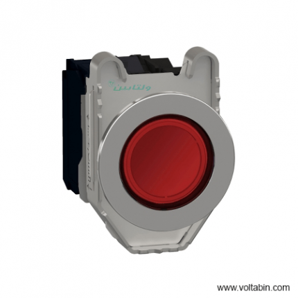
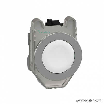
XB4FW34G5
Range of products Harmony XB4 Product or component type Illuminated push-button device short name XB4F Material bezels Chromium plated metal Fixing collar material Zamak mounting diameter 30.5mm Sale per indivisible quantity 1 Head type Built-in-flush Shape of signaling unit head Rounds Type of operator Spring returns Profile operators Red flush Operator additional information With plain lenses Contacts type and composition 1 NO + 1 NC contact operation Slow-break Connections – terminals Screw clamp terminals, <= 2 x 1.5 mm² with cable ends conforming to EN/IEC 60947-1
Screw clamp terminals, 1 x 0.22…2 x 2.5 mm² without cable ends conforming to EN/IEC 60947-1light source Universal LEDs Bulb base LED integrals [Us] rated supply voltage 110…120 V AC at 50/60 Hz Heights 47mm widths 36.6mm depth 55mm Terminals description ISO n°1 (21-22)NC
(13-14)NOproduct weight 0.132 kgs Resistance to high pressure washer 7000000 Pa at 55 °C, distance : 0.1 m Device mounting Built-ins Fix mode By screws recommended torque: 0.8 Nm Contacts usage Standard contacts Positive opening With conforming to EN/IEC 60947-5-1 appendix K Operating travel 1.5 mm (NC changing electrical state)
2.6 mm (NO changing electrical state)
4.3 mm (total travel)operating force 3.5 N NC changing electrical state
3.8 NMechanical durability 10000000 cycles Tightening torque 0.8…1.2 Nm conforming to EN 60947-1 Shape of screw head Cross compatible with Philips no 1 screwdriver
Cross compatible with pozidriv No 1 screwdriver
Slotted compatible with flat Ø 4 mm screwdriver
Slotted compatible with flat Ø 5.5 mm screwdriverContacts material Silver alloy (Ag/Ni) Short-circuit protection 10 A cartridge fuse type gG conforming to EN/IEC 60947-5-1 [Ith] conventional free air thermal current 10 A conforming to EN/IEC 60947-5-1 [Ui] rated insulation voltage 600 V (pollution degree 3) conforming to EN/IEC 60947-1 [Uimp] rated impulse withstand voltage 6 kV conforming to EN/IEC 60947-1 [Ie] rated operational current 3 A at 240 V, AC-15, A600 conforming to EN/IEC 60947-5-1
6 A at 120 V, AC-15, A600 conforming to EN/IEC 60947-5-1
0.1 A at 600 V, DC- 13, Q600 conforming to EN/IEC 60947-5-1
0.27 A at 250 V, DC-13, Q600 conforming to EN/IEC 60947-5-1
0.55 A at 125 V, DC-13, Q600 conforming to EN/IEC 60947-5-1
1.2 A at 600 V, AC-15, A600 conforming to EN/IEC 60947-5-1Electrical durability 1000000 cycles, AC-15, 2 A at 230 V, operating rate <3600 cyc/h, load factor: 0.5 conforming to EN/IEC 60947-5-1 appendix C 1000000 cycles, AC-15, 3 A at 120 V
, operating rate <3600 cyc/h, load factor: 0.5 conforming to EN/IEC 60947-5-1 appendix C
1000000 cycles, AC-15, 4 A at 24 V, operating rate <3600 cyc/h, load factor: 0.5 conforming to EN/IEC 60947-5-1 appendix C
1000000 cycles, DC-13, 0.2 A at 110 V, operating rate <3600 cyc/h, load factor: 0.5 conforming to EN/IEC 60947-5-1 appendix C 1000000
cycles , DC-13, 0.5 A at 24 V, operating rate <3600 cyc/h, load factor: 0.5 conforming to EN/IEC 60947-5-1 appendix CElectrical reliability Λ < 10exp(-6) at 5 V and 1 mA in clean environment conforming to EN/IEC 60947-5-4
Λ < 10exp(-8) at 17 V and 5 mA in clean environment conforming to EN/IEC 60947-5 -4Signaling type Steady Current consumption 14 mA service life 100000 h at rated voltage and 25 °C Surge withstand 1 kV conforming to IEC 61000-4-5 Supply voltage limits 100…132V AC Presentation devices Complete product Protective treatment Th Ambient air temperature for storage -40…70 °C Ambient air temperature for operation -40…70 °C Electrical shock protection class Class I conforming to IEC 60536 IP degree of protection IP66 conforming to IEC 60529
IP67 conforming to IEC 60529
IP69 conforming to IEC 60529
IP69K conforming to ISO 20653
Type 13 conforming to UL 50 E
Type 12 conforming to UL
50 E Type 4 conforming to UL 50 E
Type 4X conforming to UL 50 EIK degree of protection IK06 conforming to IEC 50102 standards CSA C22.2 No 14
EN/IEC 60947-5-1
EN/IEC 60947-5-4
UL 508
EN/IEC 60947-1
JIS C8201-5-1
CE
JIS C8201-1Product certifications UL listed
CSA
CCC
EACvibration resistance 5 gn (f= 10…500 Hz) conforming to IEC 60068-2-6
2 mm peak to peak (f= 2…10 Hz) conforming to IEC 60068-2-6shock resistance 30 gn (duration = 18 ms) for half sine wave acceleration conforming to IEC 60068-2-27
50 gn (duration = 11 ms) for half sine wave acceleration conforming to IEC 60068-2-27
25 gn (duration = 6 ms) for 1000 shocks on each axis conforming to IEC 60068-2-27Resistance to fast transients 2 kV conforming to IEC 61000-4-4 Resistance to electromagnetic fields 10 V/m conforming to IEC 61000-4-3 Resistance to electrostatic discharge 6 kV on contact (on metal parts) conforming to IEC 61000-4-2
8 kV in free air (in insulating parts) conforming to IEC 61000-4-2Electromagnetic emission Class B conforming to IEC 55011 Unit Type of Package 1 PCE Number of Units in Package 1 1 Package 1 Height 4.3cm Package 1 width 5.2cm Package 1 Length 8.6cm Package 1 Weight 132.0 g
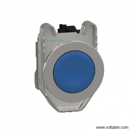
XB4FW36B5
Range of product Harmony XB4 Product or component type Illuminated push-button device short name XB4F Bezel material Chromium plated metal Fixing collar material Zamak Mounting diameter 30.5 mm Sale per indivisible quantity 1 Head type Built-in-flush Shape of signaling unit head Round Type of operator Spring return Operator profile Blue flush Operator additional information With plain lens Contacts type and composition 1 NO + 1 NC Contact operation Slow-break Connections – terminals Screw clamp terminals, <= 2 x 1.5 mm² with cable end conforming to EN/IEC 60947-1
Screw clamp terminals, 1 x 0.22…2 x 2.5 mm² without cable end conforming to EN/IEC 60947-1Light source Universal LED Bulb base Integral LED [Us] rated supply voltage 24 V AC/DC at 50/60 Hz Height 47 mm Width 36.6 mm Depth 55 mm Terminals description ISO n°1 (13-14)NO
(21-22)NCProduct weight 0.132 kg Resistance to high pressure washer 7000000 Pa at 55 °C, distance : 0.1 m Device mounting Built-in Fixing mode By screws recommended torque: 0.8 N.m Contacts usage Standard contacts Positive opening With conforming to EN/IEC 60947-5-1 appendix K Operating travel 1.5 mm (NC changing electrical state)
2.6 mm (NO changing electrical state)
4.3 mm (total travel)Operating force 3.5 N NC changing electrical state
3.8 NMechanical durability 10000000 cycles Tightening torque 0.8…1.2 N.m conforming to EN 60947-1 Shape of screw head Cross compatible with Philips no 1 screwdriver
Cross compatible with pozidriv No 1 screwdriver
Slotted compatible with flat Ø 4 mm screwdriver
Slotted compatible with flat Ø 5.5 mm screwdriverContacts material Silver alloy (Ag/Ni) Short-circuit protection 10 A cartridge fuse type gG conforming to EN/IEC 60947-5-1 [Ith] conventional free air thermal current 10 A conforming to EN/IEC 60947-5-1 [Ui] rated insulation voltage 600 V (pollution degree 3) conforming to EN/IEC 60947-1 [Uimp] rated impulse withstand voltage 6 kV conforming to EN/IEC 60947-1 [Ie] rated operational current 3 A at 240 V, AC-15, A600 conforming to EN/IEC 60947-5-1
6 A at 120 V, AC-15, A600 conforming to EN/IEC 60947-5-1
0.1 A at 600 V, DC-13, Q600 conforming to EN/IEC 60947-5-1
0.27 A at 250 V, DC-13, Q600 conforming to EN/IEC 60947-5-1
0.55 A at 125 V, DC-13, Q600 conforming to EN/IEC 60947-5-1
1.2 A at 600 V, AC-15, A600 conforming to EN/IEC 60947-5-1Electrical durability 1000000 cycles, AC-15, 2 A at 230 V, operating rate <3600 cyc/h, load factor: 0.5 conforming to EN/IEC 60947-5-1 appendix C
1000000 cycles, AC-15, 3 A at 120 V, operating rate <3600 cyc/h, load factor: 0.5 conforming to EN/IEC 60947-5-1 appendix C
1000000 cycles, AC-15, 4 A at 24 V, operating rate <3600 cyc/h, load factor: 0.5 conforming to EN/IEC 60947-5-1 appendix C
1000000 cycles, DC-13, 0.2 A at 110 V, operating rate <3600 cyc/h, load factor: 0.5 conforming to EN/IEC 60947-5-1 appendix C
1000000 cycles, DC-13, 0.5 A at 24 V, operating rate <3600 cyc/h, load factor: 0.5 conforming to EN/IEC 60947-5-1 appendix CElectrical reliability Λ < 10exp(-6) at 5 V and 1 mA in clean environment conforming to EN/IEC 60947-5-4
Λ < 10exp(-8) at 17 V and 5 mA in clean environment conforming to EN/IEC 60947-5-4Signalling type Steady Current consumption 18 mA Service life 100000 h at rated voltage and 25 °C Surge withstand 1 kV conforming to IEC 61000-4-5 Supply voltage limits 19.2…30 V DC
21.6…26.4 V ACDevice presentation Complete product Protective treatment TH Ambient air temperature for storage -40…70 °C Ambient air temperature for operation -40…70 °C Electrical shock protection class Class I conforming to IEC 60536 IP degree of protection IP66 conforming to IEC 60529
IP67 conforming to IEC 60529
IP69 conforming to IEC 60529
IP69K conforming to ISO 20653
Type 13 conforming to UL 50 E
Type 12 conforming to UL 50 E
Type 4 conforming to UL 50 E
Type 4X conforming to UL 50 EIK degree of protection IK06 conforming to IEC 50102 Standards CSA C22.2 No 14
EN/IEC 60947-5-1
EN/IEC 60947-5-4
UL 508
EN/IEC 60947-1
JIS C8201-5-1
CE
JIS C8201-1Product certifications UL listed
CSA
CCC
EACVibration resistance 5 gn (f= 10…500 Hz) conforming to IEC 60068-2-6
2 mm peak to peak (f= 2…10 Hz) conforming to IEC 60068-2-6Shock resistance 30 gn (duration = 18 ms) for half sine wave acceleration conforming to IEC 60068-2-27
50 gn (duration = 11 ms) for half sine wave acceleration conforming to IEC 60068-2-27
25 gn (duration = 6 ms) for 1000 shocks on each axis conforming to IEC 60068-2-27Resistance to fast transients 2 kV conforming to IEC 61000-4-4 Resistance to electromagnetic fields 10 V/m conforming to IEC 61000-4-3 Resistance to electrostatic discharge 6 kV on contact (on metal parts) conforming to IEC 61000-4-2
8 kV in free air (in insulating parts) conforming to IEC 61000-4-2Electromagnetic emission Class B conforming to IEC 55011 Unit Type of Package 1 PCE Number of Units in Package 1 1 Package 1 Height 8.7 cm Package 1 Width 4.3 cm Package 1 Length 5.2 cm Package 1 Weight 127 g Unit Type of Package 2 S02 Number of Units in Package 2 40 Package 2 Height 15 cm Package 2 Width 30 cm Package 2 Length 40 cm Package 2 Weight 5.372 kg
XB5AA11
Range of product Harmony XB5 Product or component type Push-button device short name XB5 Bezel material Plastic
Dark grey plasticHead type Standard Fixing collar material Plastic Mounting diameter 22 mm Sale per indivisible quantity 1 Shape of signaling unit head Round Type of operator Spring return Operator profile White flush, unmarked Contacts type and composition 1 NO Contact operation Slow-break Connections – terminals Screw clamp terminals, <= 2 x 1.5 mm² with cable end conforming to EN/IEC 60947-1
Screw clamp terminals, 1 x 0.22…2 x 2.5 mm² without cable end conforming to EN/IEC 60947-1Height 42 mm Width 30 mm Depth 52 mm Terminals description ISO n°1 (13-14)NO Product weight 0.037 kg Resistance to high pressure washer 7000000 Pa at 55 °C, distance : 0.1 m Contacts usage Standard contacts Positive opening With conforming to EN/IEC 60947-5-1 appendix K Operating travel 1.5 mm (NO changing electrical state)
2.6 mm (total travel)
4.3 mmOperating force 3.5 N NO changing electrical state
3.8 NMechanical durability 10000000 cycles Tightening torque 0.8…1.2 N.m conforming to EN 60947-1 Shape of screw head Cross compatible with Philips no 1 screwdriver
Cross compatible with pozidriv No 1 screwdriver
Slotted compatible with flat Ø 4 mm screwdriver
Slotted compatible with flat Ø 5.5 mm screwdriverContacts material Silver alloy (Ag/Ni) Short-circuit protection 10 A cartridge fuse type gG conforming to EN/IEC 60947-5-1 [Ith] conventional free air thermal current 10 A conforming to EN/IEC 60947-5-1 [Ui] rated insulation voltage 600 V (pollution degree 3) conforming to EN/IEC 60947-1 [Uimp] rated impulse withstand voltage 6 kV conforming to EN/IEC 60947-1 [Ie] rated operational current 3 A at 240 V, AC-15, A600 conforming to EN/IEC 60947-5-1
6 A at 120 V, AC-15, A600 conforming to EN/IEC 60947-5-1
0.1 A at 600 V, DC-13, Q600 conforming to EN/IEC 60947-5-1
0.27 A at 250 V, DC-13, Q600 conforming to EN/IEC 60947-5-1
0.55 A at 125 V, DC-13, Q600 conforming to EN/IEC 60947-5-1
1.2 A at 600 V, AC-15, A600 conforming to EN/IEC 60947-5-1Electrical durability 1000000 cycles AC-15, 2 A at 230 V, operating rate <3600 cyc/h, load factor: 0.5 conforming to EN/IEC 60947-5-1: appendix C
1000000 cycles AC-15, 3 A at 120 V, operating rate <3600 cyc/h, load factor: 0.5 conforming to EN/IEC 60947-5-1: appendix C
1000000 cycles AC-15, 4 A at 24 V, operating rate <3600 cyc/h, load factor: 0.5 conforming to EN/IEC 60947-5-1: appendix C
1000000 cycles DC-13, 0.2 A at 110 V, operating rate <3600 cyc/h, load factor: 0.5 conforming to EN/IEC 60947-5-1: appendix C
1000000 cycles DC-13, 0.5 A at 24 V, operating rate <3600 cyc/h, load factor: 0.5 conforming to EN/IEC 60947-5-1: appendix CElectrical reliability Λ < 10exp(-6) at 5 V and 1 mA in clean environment conforming to EN/IEC 60947-5-4
Λ < 10exp(-8) at 17 V and 5 mA in clean environment conforming to EN/IEC 60947-5-4Device presentation Complete product Customizable No Customizable 1 GCR BRIDGE XB5AACUST01 Compatibility code XB5 Protective treatment TH Ambient air temperature for storage -40…70 °C Ambient air temperature for operation -40…70 °C Overvoltage category Class II conforming to IEC 60536 IP degree of protection IP66 conforming to IEC 60529
IP67
IP69
IP69KNEMA degree of protection NEMA 13
NEMA 4XIK degree of protection IK03 conforming to IEC 50102 Standards UL 508
EN/IEC 60947-5-4
CSA C22.2 No 14
JIS C8201-5-1
EN/IEC 60947-5-1
EN/IEC 60947-1
JIS C8201-1Product certifications BV
UL listed
RINA
LROS (Lloyds register of shipping)
GL
CSA
DNVVibration resistance 5 gn (f= 2…500 Hz) conforming to IEC 60068-2-6 Shock resistance 30 gn (duration = 18 ms) for half sine wave acceleration conforming to IEC 60068-2-27
50 gn (duration = 11 ms) for half sine wave acceleration conforming to IEC 60068-2-27Unit Type of Package 1 PCE Number of Units in Package 1 1 Package 1 Height 3.5 cm Package 1 Width 5.5 cm Package 1 Length 8.5 cm Package 1 Weight 36.0 g Unit Type of Package 2 S03 Number of Units in Package 2 150 Package 2 Height 30 cm Package 2 Width 30 cm Package 2 Length 40 cm Package 2 Weight 5.833 kg
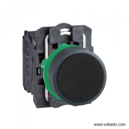
XB5AA21
Range of Product Harmony XB5 Product or Component Type Push-button device short name XB5 Bezel material Plastic
Dark grey plasticHead type Standard Fixing collar material Plastic Mounting diameter 0.87 in (22 mm) Sale per indivisible quantity 1 Shape of signaling unit head Round Type of operator Spring return Operator profile Black flush, unmarked Contacts type and composition 1 NO Contact operation Slow-break Connections – terminals Screw clamp terminals, <= 2 x 1.5 mm² with cable end EN/IEC 60947-1
Screw clamp terminals, 1 x 0.22…2 x 2.5 mm² without cable end EN/IEC 60947-1Height 1.65 in (42 mm) Width 1.18 in (30 mm) Depth 2.05 in (52 mm) Terminals description ISO n°1 (13-14)NO Product Weight 0.08 lb(US) (0.037 kg) Resistance to high pressure washer 1015.26 psi (7000000 Pa) 131 °F (55 °C) 0.1 m Contacts usage Standard contacts Positive opening Without Operating travel 0.10 in (2.6 mm) NO changing electrical state)
0.17 in (4.3 mm) total travel)Operating force 3.8 N NO changing electrical state Mechanical durability 10000000 cycles Tightening torque 7.08…10.62 lbf.in (0.8…1.2 N.m) EN 60947-1 Shape of screw head Cross Philips no 1
Cross pozidriv No 1
Slotted flat Ø 4 mm
Slotted flat Ø 5.5 mmContacts material Silver alloy (Ag/Ni) Short-circuit protection 10 A cartridge fuse gG EN/IEC 60947-5-1 [Ith] conventional free air thermal current 10 A EN/IEC 60947-5-1 [Ui] rated insulation voltage 600 V 3)EN/IEC 60947-1 [Uimp] rated impulse withstand voltage 6 kV EN/IEC 60947-1 [Ie] rated operational current 3 A 240 V, AC-15, A600 EN/IEC 60947-5-1
6 A 120 V, AC-15, A600 EN/IEC 60947-5-1
0.1 A 600 V, DC-13, Q600 EN/IEC 60947-5-1
0.27 A 250 V, DC-13, Q600 EN/IEC 60947-5-1
0.55 A 125 V, DC-13, Q600 EN/IEC 60947-5-1
1.2 A 600 V, AC-15, A600 EN/IEC 60947-5-1Electrical durability 1000000 cycles AC-15, 2 A 230 V 3600 cyc/h 0.5 EN/IEC 60947-5-1 appendix C
1000000 cycles AC-15, 3 A 120 V 3600 cyc/h 0.5 EN/IEC 60947-5-1 appendix C
1000000 cycles AC-15, 4 A 24 V 3600 cyc/h 0.5 EN/IEC 60947-5-1 appendix C
1000000 cycles DC-13, 0.2 A 110 V 3600 cyc/h 0.5 EN/IEC 60947-5-1 appendix C
1000000 cycles DC-13, 0.5 A 24 V 3600 cyc/h 0.5 EN/IEC 60947-5-1 appendix CElectrical reliability Λ < 10exp(-6) 5 V 1 mA in clean environment EN/IEC 60947-5-4
Λ < 10exp(-8) 17 V 5 mA in clean environment EN/IEC 60947-5-4Device presentation Complete product Customizable No Customizable 1 GCR BRIDGE XB5AACUST01 Compatibility code XB5 Protective treatment TH Ambient Air Temperature for Storage -40…158 °F (-40…70 °C) Ambient Air Temperature for Operation -40…158 °F (-40…70 °C) Overvoltage category Class II IEC 60536 IP degree of protection IP66 IEC 60529
IP67
IP69
IP69KNEMA degree of protection NEMA 13
NEMA 4XIK degree of protection IK03 IEC 50102 Standards EN/IEC 60947-1
UL 508
JIS C8201-5-1
EN/IEC 60947-5-4
EN/IEC 60947-5-1
CSA C22.2 No 14
JIS C8201-1Product Certifications UL Listed
CSA
RINA
BV
DNV
LROS (Lloyds register of shipping)
GLVibration resistance 5 gn 2…500 Hz)IEC 60068-2-6 Shock resistance 30 gn 18 ms) half sine wave acceleration IEC 60068-2-27
50 gn 11 ms) half sine wave acceleration IEC 60068-2-27Unit Type of Package 1 PCE Number of Units in Package 1 1 Package 1 Height 1.38 in (3.500 cm) Package 1 Width 2.17 in (5.500 cm) Package 1 Length 3.35 in (8.500 cm) Package 1 Weight 1.26 oz (35.800 g) Unit Type of Package 2 S03 Number of Units in Package 2 150 Package 2 Height 11.81 in (30.000 cm) Package 2 Width 11.81 in (30.000 cm) Package 2 Length 15.75 in (40.000 cm) Package 2 Weight 13.10 lb(US) (5.940 kg) Unit Type of Package 3 P06 Number of Units in Package 3 1200 Package 3 Height 29.53 in (75.000 cm) Package 3 Width 31.50 in (80.000 cm) Package 3 Length 23.62 in (60.000 cm) Package 3 Weight 122.40 lb(US) (55.520 kg)
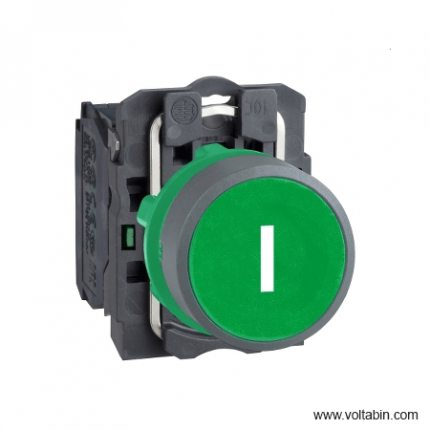
XB5AA3311C0
Range of product Harmony XB5 Product or component type Push-button Device short name XB5 Bezel material Plastic colour plated grey Head type Standard Fixing collar material Plastic Mounting diameter 22 mm Sale per indivisible quantity 1 Shape of signaling unit head Round Type of operator Spring return Operator profile Green flush, I (white) Contacts type and composition 1 NO Contact operation Slow-break Connections – terminals Screw clamp terminals, <= 2 x 1.5 mm² with cable end conforming to EN/IEC 60947-1
Screw clamp terminals, 1 x 0.22…2 x 2.5 mm² without cable end conforming to EN/IEC 60947-1Height 42 mm Width 30 mm Depth 52 mm Terminals description ISO n°1 (13-14)NO Net weight 0.037 kg Resistance to high pressure washer 7000000 Pa at 55 °C, distance : 0.1 m Contacts usage Standard contacts Positive opening Without Operating travel 2.6 mm (NO changing electrical state)
4.3 mm (total travel)Operating force 3.8 N NO changing electrical state Mechanical durability 10000000 cycles Tightening torque 0.8…1.2 N.m conforming to EN 60947-1 Shape of screw head Cross compatible with Philips no 1 screwdriver
Cross compatible with pozidriv No 1 screwdriver
Slotted compatible with flat Ø 4 mm screwdriver
Slotted compatible with flat Ø 5.5 mm screwdriverContacts material Silver alloy (Ag/Ni) Short-circuit protection 10 A cartridge fuse type gG conforming to EN/IEC 60947-5-1 [Ith] conventional free air thermal current 10 A conforming to EN/IEC 60947-5-1 [Ui] rated insulation voltage 600 V (pollution degree 3) conforming to EN/IEC 60947-1 [Uimp] rated impulse withstand voltage 6 kV conforming to EN/IEC 60947-1 [Ie] rated operational current 3 A at 240 V, AC-15, A600 conforming to EN/IEC 60947-5-1
6 A at 120 V, AC-15, A600 conforming to EN/IEC 60947-5-1
0.1 A at 600 V, DC-13, Q600 conforming to EN/IEC 60947-5-1
0.27 A at 250 V, DC-13, Q600 conforming to EN/IEC 60947-5-1
0.55 A at 125 V, DC-13, Q600 conforming to EN/IEC 60947-5-1
1.2 A at 600 V, AC-15, A600 conforming to EN/IEC 60947-5-1Electrical durability 1000000 cycles AC-15, 2 A at 230 V, operating rate <3600 cyc/h, load factor: 0.5 conforming to EN/IEC 60947-5-1: appendix C
1000000 cycles AC-15, 3 A at 120 V, operating rate <3600 cyc/h, load factor: 0.5 conforming to EN/IEC 60947-5-1: appendix C
1000000 cycles AC-15, 4 A at 24 V, operating rate <3600 cyc/h, load factor: 0.5 conforming to EN/IEC 60947-5-1: appendix C
1000000 cycles DC-13, 0.2 A at 110 V, operating rate <3600 cyc/h, load factor: 0.5 conforming to EN/IEC 60947-5-1: appendix C
1000000 cycles DC-13, 0.5 A at 24 V, operating rate <3600 cyc/h, load factor: 0.5 conforming to EN/IEC 60947-5-1: appendix CElectrical reliability Λ < 10exp(-6) at 5 V and 1 mA in clean environment conforming to EN/IEC 60947-5-4
Λ < 10exp(-8) at 17 V and 5 mA in clean environment conforming to EN/IEC 60947-5-4Device presentation Complete product Customizable No Customizable 1 GCR BRIDGE XB5AACUST06 Compatibility code XB5 Protective treatment TH Ambient air temperature for storage -40…70 °C Ambient air temperature for operation -40…70 °C Overvoltage category Class II conforming to IEC 60536 IP degree of protection IP66 conforming to IEC 60529
IP67NEMA degree of protection NEMA 13
NEMA 4XIK degree of protection IK03 conforming to IEC 50102 Standards EN/IEC 60947-5-1
CSA C22.2 No 14
UL 508
EN/IEC 60947-1
JIS C8201-5-1
EN/IEC 60947-5-4
JIS C8201-1Product certifications LROS (Lloyds register of shipping)
UL listed
DNV
CSA
BV
GL
RINAVibration resistance 5 gn (f= 2…500 Hz) conforming to IEC 60068-2-6
2 mm peak to peak (f= 2…10 Hz) conforming to IEC 60068-2-6Shock resistance 30 gn (duration = 18 ms) for half sine wave acceleration conforming to IEC 60068-2-27
50 gn (duration = 11 ms) for half sine wave acceleration conforming to IEC 60068-2-27
25 gn (duration = 6 ms) for 1000 shocks on each axis conforming to IEC 60068-2-27Unit Type of Package 1 PCE Number of Units in Package 1 1 Package 1 Height 8.6 cm Package 1 Width 3.3 cm Package 1 Length 5.2 cm Package 1 Weight 36.0 g
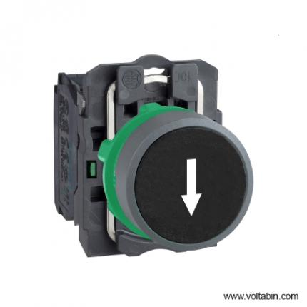
XB5AA3351C0
Range of product Harmony XB5 Product or component type Push-button device short name XB5 Bezel material Plastic colour plated grey Head type Standard Fixing collar material Plastic Mounting diameter 22 mm Sale per indivisible quantity 1 Shape of signaling unit head Round Type of operator Spring return Operator profile Black flush, down arrow (white) Contacts type and composition 1 NO Contact operation Slow-break Connections – terminals Screw clamp terminals, <= 2 x 1.5 mm² with cable end conforming to EN/IEC 60947-1
Screw clamp terminals, 1 x 0.22…2 x 2.5 mm² without cable end conforming to EN/IEC 60947-1Height 42 mm Width 30 mm Depth 52 mm Terminals description ISO n°1 (13-14)NO Product weight 0.037 kg Resistance to high pressure washer 7000000 Pa at 55 °C, distance : 0.1 m Contacts usage Standard contacts Positive opening Without Operating travel 2.6 mm (NO changing electrical state)
4.3 mm (total travel)Operating force 3.8 N NO changing electrical state Mechanical durability 10000000 cycles Tightening torque 0.8…1.2 N.m conforming to EN 60947-1 Shape of screw head Cross compatible with Philips no 1 screwdriver
Cross compatible with pozidriv No 1 screwdriver
Slotted compatible with flat Ø 4 mm screwdriver
Slotted compatible with flat Ø 5.5 mm screwdriverContacts material Silver alloy (Ag/Ni) Short-circuit protection 10 A cartridge fuse type gG conforming to EN/IEC 60947-5-1 [Ith] conventional free air thermal current 10 A conforming to EN/IEC 60947-5-1 [Ui] rated insulation voltage 600 V (pollution degree 3) conforming to EN/IEC 60947-1 [Uimp] rated impulse withstand voltage 6 kV conforming to EN/IEC 60947-1 [Ie] rated operational current 3 A at 240 V, AC-15, A600 conforming to EN/IEC 60947-5-1
6 A at 120 V, AC-15, A600 conforming to EN/IEC 60947-5-1
0.1 A at 600 V, DC-13, Q600 conforming to EN/IEC 60947-5-1
0.27 A at 250 V, DC-13, Q600 conforming to EN/IEC 60947-5-1
0.55 A at 125 V, DC-13, Q600 conforming to EN/IEC 60947-5-1
1.2 A at 600 V, AC-15, A600 conforming to EN/IEC 60947-5-1Electrical durability 1000000 cycles AC-15, 2 A at 230 V, operating rate <3600 cyc/h, load factor: 0.5 conforming to EN/IEC 60947-5-1: appendix C
1000000 cycles AC-15, 3 A at 120 V, operating rate <3600 cyc/h, load factor: 0.5 conforming to EN/IEC 60947-5-1: appendix C
1000000 cycles AC-15, 4 A at 24 V, operating rate <3600 cyc/h, load factor: 0.5 conforming to EN/IEC 60947-5-1: appendix C
1000000 cycles DC-13, 0.2 A at 110 V, operating rate <3600 cyc/h, load factor: 0.5 conforming to EN/IEC 60947-5-1: appendix C
1000000 cycles DC-13, 0.5 A at 24 V, operating rate <3600 cyc/h, load factor: 0.5 conforming to EN/IEC 60947-5-1: appendix CElectrical reliability Λ < 10exp(-6) at 5 V and 1 mA in clean environment conforming to EN/IEC 60947-5-4
Λ < 10exp(-8) at 17 V and 5 mA in clean environment conforming to EN/IEC 60947-5-4Device presentation Complete product Customizable No Customizable 1 GCR BRIDGE XB5AACUST06 Compatibility code XB5 Protective treatment TH Ambient air temperature for storage -40…70 °C Ambient air temperature for operation -40…70 °C Overvoltage category Class II conforming to IEC 60536 IP degree of protection IP66 conforming to IEC 60529
IP67NEMA degree of protection NEMA 13
NEMA 4XIK degree of protection IK03 conforming to IEC 50102 Standards CSA C22.2 No 14
JIS C8201-5-1
EN/IEC 60947-1
UL 508
EN/IEC 60947-5-1
EN/IEC 60947-5-4
JIS C8201-1Product certifications BV
GL
RINA
CSA
DNV
LROS (Lloyds register of shipping)
UL listedVibration resistance 5 gn (f= 2…500 Hz) conforming to IEC 60068-2-6
2 mm peak to peak (f= 2…10 Hz) conforming to IEC 60068-2-6Shock resistance 30 gn (duration = 18 ms) for half sine wave acceleration conforming to IEC 60068-2-27
50 gn (duration = 11 ms) for half sine wave acceleration conforming to IEC 60068-2-27
25 gn (duration = 6 ms) for 1000 shocks on each axis conforming to IEC 60068-2-27Unit Type of Package 1 PCE Number of Units in Package 1 1 Package 1 Height 5.33 cm Package 1 Width 3.56 cm Package 1 Length 8.89 cm Package 1 Weight 0.04 kg
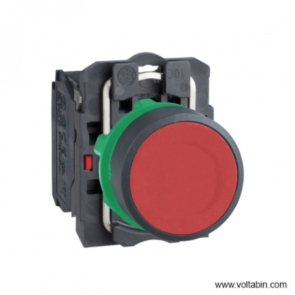
XB5AA42
Range of Product Harmony XB5 Product or Component Type Push-button device short name XB5 Bezel material Plastic
Dark grey plasticHead type Standard Fixing collar material Plastic Mounting diameter 0.87 in (22 mm) Sale per indivisible quantity 1 Shape of signaling unit head Round Type of operator Spring return Operator profile Red flush, unmarked Contacts type and composition 1 NC Contact operation Slow-break Connections – terminals Screw clamp terminals, <= 2 x 1.5 mm² with cable end EN/IEC 60947-1
Screw clamp terminals, 1 x 0.22…2 x 2.5 mm² without cable end EN/IEC 60947-1Height 1.65 in (42 mm) Width 1.18 in (30 mm) Depth 2.05 in (52 mm) Terminals description ISO n°1 (21-22)NC Product Weight 0.08 lb(US) (0.037 kg) Resistance to high pressure washer 1015.26 psi (7000000 Pa) 131 °F (55 °C) 0.1 m Contacts usage Standard contacts Positive opening With EN/IEC 60947-5-1 appendix K Operating travel 0.06 in (1.5 mm) NC changing electrical state)
0.17 in (4.3 mm) total travel)Operating force 3.5 N NC changing electrical state Mechanical durability 10000000 cycles Tightening torque 7.08…10.62 lbf.in (0.8…1.2 N.m) EN 60947-1 Shape of screw head Cross Philips no 1
Cross pozidriv No 1
Slotted flat Ø 4 mm
Slotted flat Ø 5.5 mmContacts material Silver alloy (Ag/Ni) Short-circuit protection 10 A cartridge fuse gG EN/IEC 60947-5-1 [Ith] conventional free air thermal current 10 A EN/IEC 60947-5-1 [Ui] rated insulation voltage 600 V 3)EN/IEC 60947-1 [Uimp] rated impulse withstand voltage 6 kV EN/IEC 60947-1 [Ie] rated operational current 3 A 240 V, AC-15, A600 EN/IEC 60947-5-1
6 A 120 V, AC-15, A600 EN/IEC 60947-5-1
0.1 A 600 V, DC-13, Q600 EN/IEC 60947-5-1
0.27 A 250 V, DC-13, Q600 EN/IEC 60947-5-1
0.55 A 125 V, DC-13, Q600 EN/IEC 60947-5-1
1.2 A 600 V, AC-15, A600 EN/IEC 60947-5-1Electrical durability 1000000 cycles AC-15, 2 A 230 V 3600 cyc/h 0.5 EN/IEC 60947-5-1 appendix C
1000000 cycles AC-15, 3 A 120 V 3600 cyc/h 0.5 EN/IEC 60947-5-1 appendix C
1000000 cycles AC-15, 4 A 24 V 3600 cyc/h 0.5 EN/IEC 60947-5-1 appendix C
1000000 cycles DC-13, 0.2 A 110 V 3600 cyc/h 0.5 EN/IEC 60947-5-1 appendix C
1000000 cycles DC-13, 0.5 A 24 V 3600 cyc/h 0.5 EN/IEC 60947-5-1 appendix CElectrical reliability Λ < 10exp(-6) 5 V 1 mA in clean environment EN/IEC 60947-5-4
Λ < 10exp(-8) 17 V 5 mA in clean environment EN/IEC 60947-5-4Device presentation Complete product Customizable No Customizable 1 GCR BRIDGE XB5AACUST01 Compatibility code XB5 Protective treatment TH Ambient Air Temperature for Storage -40…158 °F (-40…70 °C) Ambient Air Temperature for Operation -40…158 °F (-40…70 °C) Overvoltage category Class II IEC 60536 IP degree of protection IP66 IEC 60529
IP67
IP69
IP69KNEMA degree of protection NEMA 13
NEMA 4XIK degree of protection IK03 IEC 50102 Standards EN/IEC 60947-1
CSA C22.2 No 14
JIS C8201-5-1
UL 508
EN/IEC 60947-5-1
EN/IEC 60947-5-4
JIS C8201-1Product Certifications UL Listed
BV
GL
CSA
LROS (Lloyds register of shipping)
DNV
RINAVibration resistance 5 gn 2…500 Hz)IEC 60068-2-6 Shock resistance 30 gn 18 ms) half sine wave acceleration IEC 60068-2-27
50 gn 11 ms) half sine wave acceleration IEC 60068-2-27Unit Type of Package 1 PCE Number of Units in Package 1 1 Package 1 Height 1.38 in (3.500 cm) Package 1 Width 2.17 in (5.500 cm) Package 1 Length 3.35 in (8.500 cm) Package 1 Weight 1.26 oz (35.800 g) Unit Type of Package 2 S03 Number of Units in Package 2 150 Package 2 Height 11.81 in (30.000 cm) Package 2 Width 11.81 in (30.000 cm) Package 2 Length 15.75 in (40.000 cm) Package 2 Weight 12.66 lb(US) (5.743 kg) Unit Type of Package 3 P06 Number of Units in Package 3 1200 Package 3 Height 29.53 in (75.000 cm) Package 3 Width 31.50 in (80.000 cm) Package 3 Length 23.62 in (60.000 cm) Package 3 Weight 118.92 lb(US) (53.941 kg)