
همه محصولات
- اشنایدر الکتریک589 محصول
- overcurrent-relay-schneider-electric0 محصول
- اتوماسیون صنعتی (PLC)229 محصول
- الکتریکال262 محصول
- درایو – اینورتر52 محصول
- سافت استارتر46 محصول
- زیمنس3,624 محصول
- همه محصولات3,619 محصول
فیلترها
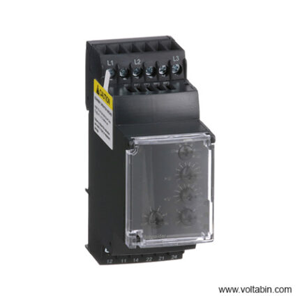
RM35TF30
range of product Harmony Control Relays product or component type 3-phase control relay relay type Multifunction control relay product specific application For 3-phase supply relay name RM35TF relay monitored parameters Undervoltage and overvoltage in window mode
Phase sequence
Phase failure detection
Asymmetrytime delay Adjustable 0.1…10 s, +/- 10 % of the full scale value switching capacity in VA 1250 VA measurement range 220…480 V voltage AC contacts type and composition 2 C/O [Uc] control circuit voltage 220…480 V reset time 1500 ms at 480 V maximum switching voltage 250 V AC
250 V DCminimum switching current 10 mA at 5 V DC maximum switching current 5 A AC
5 A DCsupply voltage limits 194…528 V AC, 3 phases control circuit voltage limits – 12 % + 10 % Un power consumption in VA 0…22 VA at 400 V AC 50 Hz voltage detection threshold < 194 V control circuit frequency 50…60 Hz +/- 10 % output contacts 2 C/O nominal output current 5 A measurement voltage limits 176…528 V AC hysteresis 2 % delay at power up 650 ms maximum measuring cycle 140 ms measurement cycle as true rms value threshold adjustment voltage -20…-2 % in the range 380…480 V AC
2…20 % of Un selected
-12…-2 % in the range 220 V AC
+2…+20 % in the range 220…440 V AC
+2…+10 % in the range 480 V ACvoltage range 220…480 V phase to phase adjustment of asymmetry threshold 5…15 % of Un selected repeat accuracy 0.3 % for time delay
0.5 % for input and measurement circuitmeasurement error < 1 % over the whole range with voltage variation
0.05 %/°C with temperature variationresponse time < 200 ms (in the event of a fault) marking CE overvoltage category III conforming to IEC 60664-1 insulation resistance > 500 MOhm at 500 V DC conforming to IEC 60255-5
> 500 MOhm at 500 V DC conforming to IEC 60664-1[Ui] rated insulation voltage 400 V conforming to IEC 60664-1 supply frequency 50/60 Hz +/- 10 % operating position Any position without derating connections – terminals Screw terminals, 1 x 0.5…1 x 4 mm² (AWG 20…AWG 11) solid without cable end
Screw terminals, 2 x 0.5…2 x 2.5 mm² (AWG 20…AWG 14) solid without cable end
Screw terminals, 1 x 0.2…1 x 2.5 mm² (AWG 24…AWG 12) flexible with cable end
Screw terminals, 2 x 0.2…2 x 1.5 mm² (AWG 24…AWG 16) flexible with cable endtightening torque 0.6…1 N.m conforming to IEC 60947-1 housing material Self-extinguishing plastic local signalling LED (green) for power ON
LED (yellow) for relay ON
LED (yellow) for faultmounting support 35 mm symmetrical DIN rail conforming to EN/IEC 60715 electrical durability 100000 cycles mechanical durability 30000000 cycles operating rate <= 360 operations/hour full load utilisation category AC-12 conforming to IEC 60947-5-1
AC-13 conforming to IEC 60947-5-1
AC-14 conforming to IEC 60947-5-1
AC-15 conforming to IEC 60947-5-1
DC-12 conforming to IEC 60947-5-1
DC-13 conforming to IEC 60947-5-1safety reliability data MTTFd = 399.5 years
B10d = 360000width 35 mm net weight 0.13 kg electromagnetic compatibility Emission standard for industrial environments conforming to EN/IEC 61000-6-4
Emission standard for residential, commercial and light-industrial environments conforming to EN/IEC 61000-6-3
Immunity for industrial environments conforming to EN/IEC 61000-6-2standards EN/IEC 60255-1 product certifications GL
UL
CSA
GOST
C-Tickdirectives 89/336/EEC – electromagnetic compatibility
73/23/EEC – low voltage directiveambient air temperature for storage -40…70 °C ambient air temperature for operation -20…50 °C relative humidity 95 % at 55 °C conforming to IEC 60068-2-30 vibration resistance 0.35 mm (f= 5…57.6 Hz) conforming to IEC 60068-2-6
1 gn (f= 57.6…150 Hz) conforming to IEC 60255-21-1shock resistance 15 gn for 11 ms conforming to IEC 60255-21-1 IP degree of protection IP20 (terminals) conforming to IEC 60529
IP30 (casing) conforming to IEC 60529pollution degree 3 conforming to IEC 60664-1 dielectric test voltage 2 kV, 1 min AC 50 Hz non-dissipating shock wave 4 kV
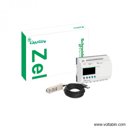
SR2PACK2BD
- Reverse polarity protection
- Simple ladder programming, adapted for non-specialists
- Discovery package, coming with Zelio Soft programming software: the simplest way to learn and use this relay
- Built-in EEPROM flash memory for data backup up to 10 years: easy-to-recover after a power shortage or incident
- CSA, C-Tick, GOST, GL and UL certified
-
Range of product Zelio Logic Product or component type Compact discovery packs Discrete input number 12 conforming to EN/IEC 61131-2 type 1 Number of outputs 8 relay kit composition SR2B201BD
Cable PC SR2USB01 for connection to PCInput/output number 20 local display With Number or control scheme lines 120 with ladder programming
0…200 with FBD programmingCycle time 6…90 ms Backup time 10 years at 25 °C Clock drift 12 min/year at 0…55 °C
6 s/month at 25 °CChecks Program memory on each power up [Us] rated supply voltage 24 V Supply voltage limits 19.2…30 V Maximum supply current 100 mA (without extension) Power dissipation in W 6 W without extension Reverse polarity protection With Discrete input type Resistive Discrete input voltage 24 V DC Discrete input current 4 mA Counting frequency 1 kHz for discrete input Voltage state 1 guaranteed >= 15 V for I1…IA and IH…IR discrete input circuit
>= 15 V for IB…IG used as discrete input circuitVoltage state 0 guaranteed <= 5 V for I1…IA and IH…IR discrete input circuit
<= 5 V for IB…IG used as discrete input circuitCurrent state 1 guaranteed >= 1.2 mA (IB…IG used as discrete input circuit)
>= 2.2 mA (I1…IA and IH…IR discrete input circuit)Current state 0 guaranteed <= 0.5 mA (IB…IG used as discrete input circuit) Input compatibility 3-wire proximity sensors PNP for discrete input Analogue input number 2 Analogue input type Common mode Analogue input range 0…10 V
0…24 VTemperature probe type NTC 10k at 25 °C
NTC 1000k at 25 °C
KTY81 210/220/221/222/250
Pt 500Maximum permissible voltage 30 V for analogue input circuit Analogue input resolution 8 bits LSB value 39 mV for analogue input circuit Conversion time Smart relay cycle time for analogue input circuit Conversion error +/- 5 % at 25 °C for analogue input circuit
+/- 6.2 % at 55 °C for analogue input circuitRepeat accuracy +/- 2 % at 55 °C for analogue input circuit Operating distance 10 m between stations, with screened cable (sensor not isolated) for analogue input circuit Input impedance 12 kOhm for IB…IG used as analogue input circuit
12 kOhm for IB…IG used as discrete input circuit
7.4 kOhm for I1…IA and IH…IR discrete input circuitOutput voltage limits 24…250 V AC (relay output)
5…30 V DC (relay output)Contacts type and composition NO for relay output Output thermal current 8 A for all 8 outputs for relay output Electrical durability AC-12: 500000 cycles at 230 V, 1.5 A for relay output conforming to EN/IEC 60947-5-1
AC-15: 500000 cycles at 230 V, 0.9 A for relay output conforming to EN/IEC 60947-5-1
DC-12: 500000 cycles at 24 V, 1.5 A for relay output conforming to EN/IEC 60947-5-1
DC-13: 500000 cycles at 24 V, 0.6 A for relay output conforming to EN/IEC 60947-5-1Switching capacity in mA >= 10 mA at 12 V (relay output) Operating rate in Hz 0.1 Hz (at Ie) for relay output
10 Hz (no load) for relay outputMechanical durability 10000000 cycles for relay output [Uimp] rated impulse withstand voltage 4 kV conforming to EN/IEC 60947-1 and EN/IEC 60664-1 Clock Without Response time 10 ms (from state 0 to state 1) for relay output
5 ms (from state 1 to state 0) for relay outputConnections – terminals Screw terminals, 1 x 0.2…1 x 2.5 mm² (AWG 25…AWG 14) semi-solid
Screw terminals, 1 x 0.2…1 x 2.5 mm² (AWG 25…AWG 14) solid
Screw terminals, 1 x 0.25…1 x 2.5 mm² (AWG 24…AWG 14) flexible with cable end
Screw terminals, 2 x 0.2…2 x 1.5 mm² (AWG 24…AWG 16) solid
Screw terminals, 2 x 0.25…2 x 0.75 mm² (AWG 24…AWG 18) flexible with cable endTightening torque 0.5 N.m Overvoltage category III conforming to EN/IEC 60664-1 Net weight 0.7 kg Immunity to microbreaks 1 ms Product certifications GOST
C-Tick
UL
GL
CSAStandards EN/IEC 61000-4-6 level 3
EN/IEC 61000-4-3
EN/IEC 60068-2-27 Ea
EN/IEC 61000-4-11
EN/IEC 61000-4-12
EN/IEC 60068-2-6 Fc
EN/IEC 61000-4-5
EN/IEC 61000-4-2 level 3
EN/IEC 61000-4-4 level 3IP degree of protection IP20 (terminal block) conforming to IEC 60529
IP40 (front panel) conforming to IEC 60529Environmental characteristic EMC directive conforming to EN/IEC 61000-6-2
EMC directive conforming to EN/IEC 61000-6-3
EMC directive conforming to EN/IEC 61000-6-4
EMC directive conforming to EN/IEC 61131-2 zone B
Low voltage directive conforming to EN/IEC 61131-2Disturbance radiated/conducted Class B conforming to EN 55022-11 group 1 Pollution degree 2 conforming to EN/IEC 61131-2 Ambient air temperature for operation -20…40 °C in non-ventilated enclosure conforming to IEC 60068-2-1 and IEC 60068-2-2
-20…55 °C conforming to IEC 60068-2-1 and IEC 60068-2-2Ambient air temperature for storage -40…70 °C Operating altitude 2000 m Maximum altitude transport 3048 m Relative humidity 95 % without condensation or dripping water Unit Type of Package 1 PCE Number of Units in Package 1 1 Package 1 Height 6.2 cm Package 1 Width 15.3 cm Package 1 Length 23.3 cm Package 1 Weight 502 g Unit Type of Package 2 S03 Number of Units in Package 2 10 Package 2 Height 30 cm Package 2 Width 30 cm Package 2 Length 40 cm Package 2 Weight 5.516 kg
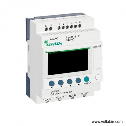
SR3B101B
-
range of product Easy Altivar 610 product or component type Variable speed drive product specific application Fan, pump, compressor, conveyor device short name ATV610 variant Standard version product destination Asynchronous motors mounting mode Cabinet mount EMC filter Integrated conforming to EN/IEC 61800-3 category C3 with 50 m IP degree of protection IP20 type of cooling Forced convection supply frequency 50…60 Hz +/-5 % network number of phases 3 phases [Us] rated supply voltage 380…460 V – 15…10 % motor power kW 110 kW for normal duty 90 kW for heavy duty motor power hp 150 hp for normal duty 125 hp for heavy duty line current 201 A at 380 V (normal duty) 175.7 A at 460 V (normal duty) 170 A at 380 V (heavy duty) 149.1 A at 460 V (heavy duty) prospective line Isc 50 kA apparent power 140.0 kVA at 460 V (normal duty) 118.8 kVA at 460 V (heavy duty) continuous output current 211 A at 2.5 kHz for normal duty 173 A at 2.5 kHz for heavy duty maximum transient current 232 A during 60 s (normal duty) 260 A during 60 s (heavy duty) asynchronous motor control profile Variable torque standard Optimized torque mode Constant torque standard output frequency 0.0001…0.5 kHz nominal switching frequency 2.5 kHz switching frequency 1…8 kHz adjustable number of preset speeds 16 preset speeds communication port protocol Modbus serial option card Slot A: communication card, Profibus DP V1 Slot A: digital or analog I/O extension card Slot A: relay output card output voltage <= power supply voltage motor slip compensation Can be suppressed Adjustable Not available in permanent magnet motor law Automatic whatever the load acceleration and deceleration ramps Linear adjustable separately from 0.01 to 9000 s S, U or customized braking to standstill By DC injection protection type Thermal protection: motor Motor phase break: motor Thermal protection: drive Overheating: drive Overcurrent between output phases and earth: drive Overload of output voltage: drive Short-circuit protection: drive Motor phase break: drive Overvoltages on the DC bus: drive Line supply overvoltage: drive Line supply undervoltage: drive Line supply phase loss: drive Overspeed: drive Break on the control circuit: drive frequency resolution Display unit: 0.1 Hz Analog input: 0.012/50 Hz electrical connection Control, screw terminal: 0.5…1.5 mm² Line side, screw terminal: 2 x 50…3 x 120 mm² Motor, screw terminal: 3 x 50…3 x 120 mm² connector type 1 RJ45 (on the remote graphic terminal) for Modbus serial physical interface 2-wire RS 485 for Modbus serial transmission frame RTU for Modbus serial transmission rate 4.8, 9.6, 19.2, 38.4 kbit/s for Modbus serial type of polarization No impedance for Modbus serial number of addresses 1…247 for Modbus serial method of access Slave supply External supply for digital inputs: 24 V DC (19…30 V), <1.25 mA, protection type: overload and short-circuit protection Internal supply for reference potentiometer (1 to 10 kOhm): 10.5 V DC +/- 5 %, <10 mA, protection type: overload and short-circuit protection local signalling 2 LEDs for local diagnostic 1 LED (yellow) for embedded communication status 2 LEDs (dual colour) for communication module status 1 LED (red) for presence of voltage width 320 mm height 852 mm 1159 mm with IP21 conformity kit depth 390 mm net weight 82 kg analogue input number 3 analogue input type AI1, AI2, AI3 software-configurable voltage: 0…10 V DC, impedance: 30 kOhm, resolution 12 bits AI1, AI2, AI3 software-configurable current: 0…20 mA, impedance: 250 Ohm, resolution 12 bits AI2, AI3 software-configurable temperature probe or water level sensor discrete input number 6 discrete input type DI1…DI6 programmable as logic input, 24 V DC (<= 30 V), impedance: 3.5 kOhm DI5, DI6 programmable as pulse input: 0…30 kHz, 24 V DC (<= 30 V) input compatibility DI1…DI6: logic input level 1 PLC conforming to EN/IEC 61131-2 DI5, DI6: pulse input level 1 PLC conforming to IEC 65A-68 discrete input logic Positive logic (source): DI1…DI6 configurable logic input, < 5 V (state 0), > 11 V (state 1) Negative logic (sink): DI1…DI6 configurable logic input, > 16 V (state 0), < 10 V (state 1) Positive logic (source): DI5, DI6 configurable pulse input, < 0.6 V (state 0), > 2.5 V (state 1) analogue output number 2 analogue output type Software-configurable current AQ1, AQ2: 0…20 mA, resolution 10 bits Software-configurable voltage AQ1, AQ2: 0…10 V DC impedance 470 Ohm, resolution 10 bits sampling duration 5 ms +/- 0.1 ms (AI1, AI2, AI3) – analog input 2 ms +/- 0.5 ms (DI1…DI6)configurable – discrete input 5 ms +/- 1 ms (DI5, DI6)configurable – pulse input 10 ms +/- 1 ms (AQ1, AQ2) – analog output accuracy +/- 0.6 % AI1, AI2, AI3 for a temperature variation 60 °C analog input +/- 1 % AQ1, AQ2 for a temperature variation 60 °C analog output linearity error AI1, AI2, AI3: +/- 0.15 % of maximum value for analog input AQ1, AQ2: +/- 0.2 % for analog output relay output number 3 relay output type Configurable relay logic R1: fault relay NO/NC electrical durability 100000 cycles Configurable relay logic R2: sequence relay NO electrical durability 100000 cycles Configurable relay logic R3: sequence relay NO electrical durability 100000 cycles refresh time Relay output (R1, R2, R3): 5 ms (+/- 0.5 ms) minimum switching current Relay output R1, R2, R3: 5 mA at 24 V DC maximum switching current Relay output R1, R2, R3 on resistive load, cos phi = 1: 3 A at 250 V AC Relay output R1, R2, R3 on resistive load, cos phi = 1: 3 A at 30 V DC Relay output R1, R2, R3 on inductive load, cos phi = 0.4 and L/R = 7 ms: 2 A at 250 V AC Relay output R1, R2, R3 on inductive load, cos phi = 0.4 and L/R = 7 ms: 2 A at 30 V DC isolation Between power and control terminals insulation resistance > 1 MOhm 500 V DC for 1 minute to earth noise level 76 dB conforming to 86/188/EEC power dissipation in W 2026 W(forced convection) at 380 V, switching frequency 2.5 kHz operating position Vertical +/- 10 degree electromagnetic compatibility Electrostatic discharge immunity test level 3 conforming to IEC 61000-4-2 Radiated radio-frequency electromagnetic field immunity test level 3 conforming to IEC 61000-4-3 Electrical fast transient/burst immunity test level 4 conforming to IEC 61000-4-4 1.2/50 µs – 8/20 µs surge immunity test level 3 conforming to IEC 61000-4-5 Conducted radio-frequency immunity test level 3 conforming to IEC 61000-4-6 pollution degree 2 conforming to EN/IEC 61800-5-1 vibration resistance 1.5 mm peak to peak (f= 2…13 Hz) conforming to IEC 60068-2-6 1 gn (f= 13…200 Hz) conforming to IEC 60068-2-6 shock resistance 6 gn for 11 ms conforming to IEC 60068-2-27 relative humidity 5…95 % without condensation conforming to IEC 60068-2-3 ambient air temperature for operation -15…45 °C (without derating) 45…60 °C (with derating factor) operating altitude <= 1000 m without derating 1000…4800 m with current derating 1 % per 100 m environmental characteristic Chemical pollution resistance class 3C3 conforming to EN/IEC 60721-3-3 Dust pollution resistance class 3S3 conforming to EN/IEC 60721-3-3 standards EN/IEC 61800-3 Environment 2 category C3 EN/IEC 61800-3 EN/IEC 61800-5-1 IEC 60721-3 marking CE Unit Type of Package 1 PCE Number of Units in Package 1 1 Package 1 Weight 96.344 kg Package 1 Height 47 cm Package 1 width 67 cm Package 1 Length 103 cm

UG4615-1CR20
|
||||||||||||||||||||||||||||||||||||||||||||||||||||||||||||||||||||||||||||||||||||||||||||||||||||||

XB4BA21
range of product
Easy Altivar 610
product or component type
Variable speed drive
product specific application
Fan, pump, compressor, conveyor
device short name
ATV610
variant
Standard version
product destination
Asynchronous motors
mounting mode
Cabinet mount
EMC filter
Integrated conforming to EN/IEC 61800-3 category C3 with 50 m
IP degree of protection
IP20
type of cooling
Forced convection
supply frequency
50…60 Hz +/-5 %
network number of phases
3 phases
[Us] rated supply voltage
380…460 V – 15…10 %
motor power kW
110 kW for normal duty
90 kW for heavy duty
motor power hp
150 hp for normal duty
125 hp for heavy duty
line current
201 A at 380 V (normal duty)
175.7 A at 460 V (normal duty)
170 A at 380 V (heavy duty)
149.1 A at 460 V (heavy duty)
prospective line Isc
50 kA
apparent power
140.0 kVA at 460 V (normal duty)
118.8 kVA at 460 V (heavy duty)
continuous output current
211 A at 2.5 kHz for normal duty
173 A at 2.5 kHz for heavy duty
maximum transient current
232 A during 60 s (normal duty)
260 A during 60 s (heavy duty)
asynchronous motor control profile
Variable torque standard
Optimized torque mode
Constant torque standard
output frequency
0.0001…0.5 kHz
nominal switching frequency
2.5 kHz
switching frequency
1…8 kHz adjustable
number of preset speeds
16 preset speeds
communication port protocol
Modbus serial
option card
Slot A: communication card, Profibus DP V1
Slot A: digital or analog I/O extension card
Slot A: relay output card
output voltage
<= power supply voltage
motor slip compensation
Can be suppressed
Adjustable
Not available in permanent magnet motor law
Automatic whatever the load
acceleration and deceleration ramps
Linear adjustable separately from 0.01 to 9000 s
S, U or customized
braking to standstill
By DC injection
protection type
Thermal protection: motor
Motor phase break: motor
Thermal protection: drive
Overheating: drive
Overcurrent between output phases and earth: drive
Overload of output voltage: drive
Short-circuit protection: drive
Motor phase break: drive
Overvoltages on the DC bus: drive
Line supply overvoltage: drive
Line supply undervoltage: drive
Line supply phase loss: drive
Overspeed: drive
Break on the control circuit: drive
frequency resolution
Display unit: 0.1 Hz
Analog input: 0.012/50 Hz
electrical connection
Control, screw terminal: 0.5…1.5 mm²
Line side, screw terminal: 2 x 50…3 x 120 mm²
Motor, screw terminal: 3 x 50…3 x 120 mm²
connector type
1 RJ45 (on the remote graphic terminal) for Modbus serial
physical interface
2-wire RS 485 for Modbus serial
transmission frame
RTU for Modbus serial
transmission rate
4.8, 9.6, 19.2, 38.4 kbit/s for Modbus serial
type of polarization
No impedance for Modbus serial
number of addresses
1…247 for Modbus serial
method of access
Slave
supply
External supply for digital inputs: 24 V DC (19…30 V), <1.25 mA, protection type: overload and short-circuit protection
Internal supply for reference potentiometer (1 to 10 kOhm): 10.5 V DC +/- 5 %, <10 mA, protection type: overload and short-circuit protection
local signalling
2 LEDs for local diagnostic
1 LED (yellow) for embedded communication status
2 LEDs (dual colour) for communication module status
1 LED (red) for presence of voltage
width
320 mm
height
852 mm
1159 mm with IP21 conformity kit
depth
390 mm
net weight
82 kg
analogue input number
3
analogue input type
AI1, AI2, AI3 software-configurable voltage: 0…10 V DC, impedance: 30 kOhm, resolution 12 bits
AI1, AI2, AI3 software-configurable current: 0…20 mA, impedance: 250 Ohm, resolution 12 bits
AI2, AI3 software-configurable temperature probe or water level sensor
discrete input number
6
discrete input type
DI1…DI6 programmable as logic input, 24 V DC (<= 30 V), impedance: 3.5 kOhm
DI5, DI6 programmable as pulse input: 0…30 kHz, 24 V DC (<= 30 V)
input compatibility
DI1…DI6: logic input level 1 PLC conforming to EN/IEC 61131-2
DI5, DI6: pulse input level 1 PLC conforming to IEC 65A-68
discrete input logic
Positive logic (source): DI1…DI6 configurable logic input, < 5 V (state 0), > 11 V (state 1)
Negative logic (sink): DI1…DI6 configurable logic input, > 16 V (state 0), < 10 V (state 1)
Positive logic (source): DI5, DI6 configurable pulse input, < 0.6 V (state 0), > 2.5 V (state 1)
analogue output number
2
analogue output type
Software-configurable current AQ1, AQ2: 0…20 mA, resolution 10 bits
Software-configurable voltage AQ1, AQ2: 0…10 V DC impedance 470 Ohm, resolution 10 bits
sampling duration
5 ms +/- 0.1 ms (AI1, AI2, AI3) – analog input
2 ms +/- 0.5 ms (DI1…DI6)configurable – discrete input
5 ms +/- 1 ms (DI5, DI6)configurable – pulse input
10 ms +/- 1 ms (AQ1, AQ2) – analog output
accuracy
+/- 0.6 % AI1, AI2, AI3 for a temperature variation 60 °C analog input
+/- 1 % AQ1, AQ2 for a temperature variation 60 °C analog output
linearity error
AI1, AI2, AI3: +/- 0.15 % of maximum value for analog input
AQ1, AQ2: +/- 0.2 % for analog output
relay output number
3
relay output type
Configurable relay logic R1: fault relay NO/NC electrical durability 100000 cycles
Configurable relay logic R2: sequence relay NO electrical durability 100000 cycles
Configurable relay logic R3: sequence relay NO electrical durability 100000 cycles
refresh time
Relay output (R1, R2, R3): 5 ms (+/- 0.5 ms)
minimum switching current
Relay output R1, R2, R3: 5 mA at 24 V DC
maximum switching current
Relay output R1, R2, R3 on resistive load, cos phi = 1: 3 A at 250 V AC
Relay output R1, R2, R3 on resistive load, cos phi = 1: 3 A at 30 V DC
Relay output R1, R2, R3 on inductive load, cos phi = 0.4 and L/R = 7 ms: 2 A at 250 V AC
Relay output R1, R2, R3 on inductive load, cos phi = 0.4 and L/R = 7 ms: 2 A at 30 V DC
isolation
Between power and control terminals
insulation resistance
> 1 MOhm 500 V DC for 1 minute to earth
noise level
76 dB conforming to 86/188/EEC
power dissipation in W
2026 W(forced convection) at 380 V, switching frequency 2.5 kHz
operating position
Vertical +/- 10 degree
electromagnetic compatibility
Electrostatic discharge immunity test level 3 conforming to IEC 61000-4-2
Radiated radio-frequency electromagnetic field immunity test level 3 conforming to IEC 61000-4-3
Electrical fast transient/burst immunity test level 4 conforming to IEC 61000-4-4
1.2/50 µs – 8/20 µs surge immunity test level 3 conforming to IEC 61000-4-5
Conducted radio-frequency immunity test level 3 conforming to IEC 61000-4-6
pollution degree
2 conforming to EN/IEC 61800-5-1
vibration resistance
1.5 mm peak to peak (f= 2…13 Hz) conforming to IEC 60068-2-6
1 gn (f= 13…200 Hz) conforming to IEC 60068-2-6
shock resistance
6 gn for 11 ms conforming to IEC 60068-2-27
relative humidity
5…95 % without condensation conforming to IEC 60068-2-3
ambient air temperature for operation
-15…45 °C (without derating)
45…60 °C (with derating factor)
operating altitude
<= 1000 m without derating
1000…4800 m with current derating 1 % per 100 m
environmental characteristic
Chemical pollution resistance class 3C3 conforming to EN/IEC 60721-3-3
Dust pollution resistance class 3S3 conforming to EN/IEC 60721-3-3
standards
EN/IEC 61800-3
Environment 2 category C3 EN/IEC 61800-3
EN/IEC 61800-5-1
IEC 60721-3
marking
CE
Unit Type of Package 1
PCE
Number of Units in Package 1
1
Package 1 Weight
96.344 kg
Package 1 Height
47 cm
Package 1 width
67 cm
Package 1 Length
103 cm
XB4BA22
range of product
Easy Altivar 610
product or component type
Variable speed drive
product specific application
Fan, pump, compressor, conveyor
device short name
ATV610
variant
Standard version
product destination
Asynchronous motors
mounting mode
Cabinet mount
EMC filter
Integrated conforming to EN/IEC 61800-3 category C3 with 50 m
IP degree of protection
IP20
type of cooling
Forced convection
supply frequency
50…60 Hz +/-5 %
network number of phases
3 phases
[Us] rated supply voltage
380…460 V – 15…10 %
motor power kW
110 kW for normal duty
90 kW for heavy duty
motor power hp
150 hp for normal duty
125 hp for heavy duty
line current
201 A at 380 V (normal duty)
175.7 A at 460 V (normal duty)
170 A at 380 V (heavy duty)
149.1 A at 460 V (heavy duty)
prospective line Isc
50 kA
apparent power
140.0 kVA at 460 V (normal duty)
118.8 kVA at 460 V (heavy duty)
continuous output current
211 A at 2.5 kHz for normal duty
173 A at 2.5 kHz for heavy duty
maximum transient current
232 A during 60 s (normal duty)
260 A during 60 s (heavy duty)
asynchronous motor control profile
Variable torque standard
Optimized torque mode
Constant torque standard
output frequency
0.0001…0.5 kHz
nominal switching frequency
2.5 kHz
switching frequency
1…8 kHz adjustable
number of preset speeds
16 preset speeds
communication port protocol
Modbus serial
option card
Slot A: communication card, Profibus DP V1
Slot A: digital or analog I/O extension card
Slot A: relay output card
output voltage
<= power supply voltage
motor slip compensation
Can be suppressed
Adjustable
Not available in permanent magnet motor law
Automatic whatever the load
acceleration and deceleration ramps
Linear adjustable separately from 0.01 to 9000 s
S, U or customized
braking to standstill
By DC injection
protection type
Thermal protection: motor
Motor phase break: motor
Thermal protection: drive
Overheating: drive
Overcurrent between output phases and earth: drive
Overload of output voltage: drive
Short-circuit protection: drive
Motor phase break: drive
Overvoltages on the DC bus: drive
Line supply overvoltage: drive
Line supply undervoltage: drive
Line supply phase loss: drive
Overspeed: drive
Break on the control circuit: drive
frequency resolution
Display unit: 0.1 Hz
Analog input: 0.012/50 Hz
electrical connection
Control, screw terminal: 0.5…1.5 mm²
Line side, screw terminal: 2 x 50…3 x 120 mm²
Motor, screw terminal: 3 x 50…3 x 120 mm²
connector type
1 RJ45 (on the remote graphic terminal) for Modbus serial
physical interface
2-wire RS 485 for Modbus serial
transmission frame
RTU for Modbus serial
transmission rate
4.8, 9.6, 19.2, 38.4 kbit/s for Modbus serial
type of polarization
No impedance for Modbus serial
number of addresses
1…247 for Modbus serial
method of access
Slave
supply
External supply for digital inputs: 24 V DC (19…30 V), <1.25 mA, protection type: overload and short-circuit protection
Internal supply for reference potentiometer (1 to 10 kOhm): 10.5 V DC +/- 5 %, <10 mA, protection type: overload and short-circuit protection
local signalling
2 LEDs for local diagnostic
1 LED (yellow) for embedded communication status
2 LEDs (dual colour) for communication module status
1 LED (red) for presence of voltage
width
320 mm
height
852 mm
1159 mm with IP21 conformity kit
depth
390 mm
net weight
82 kg
analogue input number
3
analogue input type
AI1, AI2, AI3 software-configurable voltage: 0…10 V DC, impedance: 30 kOhm, resolution 12 bits
AI1, AI2, AI3 software-configurable current: 0…20 mA, impedance: 250 Ohm, resolution 12 bits
AI2, AI3 software-configurable temperature probe or water level sensor
discrete input number
6
discrete input type
DI1…DI6 programmable as logic input, 24 V DC (<= 30 V), impedance: 3.5 kOhm
DI5, DI6 programmable as pulse input: 0…30 kHz, 24 V DC (<= 30 V)
input compatibility
DI1…DI6: logic input level 1 PLC conforming to EN/IEC 61131-2
DI5, DI6: pulse input level 1 PLC conforming to IEC 65A-68
discrete input logic
Positive logic (source): DI1…DI6 configurable logic input, < 5 V (state 0), > 11 V (state 1)
Negative logic (sink): DI1…DI6 configurable logic input, > 16 V (state 0), < 10 V (state 1)
Positive logic (source): DI5, DI6 configurable pulse input, < 0.6 V (state 0), > 2.5 V (state 1)
analogue output number
2
analogue output type
Software-configurable current AQ1, AQ2: 0…20 mA, resolution 10 bits
Software-configurable voltage AQ1, AQ2: 0…10 V DC impedance 470 Ohm, resolution 10 bits
sampling duration
5 ms +/- 0.1 ms (AI1, AI2, AI3) – analog input
2 ms +/- 0.5 ms (DI1…DI6)configurable – discrete input
5 ms +/- 1 ms (DI5, DI6)configurable – pulse input
10 ms +/- 1 ms (AQ1, AQ2) – analog output
accuracy
+/- 0.6 % AI1, AI2, AI3 for a temperature variation 60 °C analog input
+/- 1 % AQ1, AQ2 for a temperature variation 60 °C analog output
linearity error
AI1, AI2, AI3: +/- 0.15 % of maximum value for analog input
AQ1, AQ2: +/- 0.2 % for analog output
relay output number
3
relay output type
Configurable relay logic R1: fault relay NO/NC electrical durability 100000 cycles
Configurable relay logic R2: sequence relay NO electrical durability 100000 cycles
Configurable relay logic R3: sequence relay NO electrical durability 100000 cycles
refresh time
Relay output (R1, R2, R3): 5 ms (+/- 0.5 ms)
minimum switching current
Relay output R1, R2, R3: 5 mA at 24 V DC
maximum switching current
Relay output R1, R2, R3 on resistive load, cos phi = 1: 3 A at 250 V AC
Relay output R1, R2, R3 on resistive load, cos phi = 1: 3 A at 30 V DC
Relay output R1, R2, R3 on inductive load, cos phi = 0.4 and L/R = 7 ms: 2 A at 250 V AC
Relay output R1, R2, R3 on inductive load, cos phi = 0.4 and L/R = 7 ms: 2 A at 30 V DC
isolation
Between power and control terminals
insulation resistance
> 1 MOhm 500 V DC for 1 minute to earth
noise level
76 dB conforming to 86/188/EEC
power dissipation in W
2026 W(forced convection) at 380 V, switching frequency 2.5 kHz
operating position
Vertical +/- 10 degree
electromagnetic compatibility
Electrostatic discharge immunity test level 3 conforming to IEC 61000-4-2
Radiated radio-frequency electromagnetic field immunity test level 3 conforming to IEC 61000-4-3
Electrical fast transient/burst immunity test level 4 conforming to IEC 61000-4-4
1.2/50 µs – 8/20 µs surge immunity test level 3 conforming to IEC 61000-4-5
Conducted radio-frequency immunity test level 3 conforming to IEC 61000-4-6
pollution degree
2 conforming to EN/IEC 61800-5-1
vibration resistance
1.5 mm peak to peak (f= 2…13 Hz) conforming to IEC 60068-2-6
1 gn (f= 13…200 Hz) conforming to IEC 60068-2-6
shock resistance
6 gn for 11 ms conforming to IEC 60068-2-27
relative humidity
5…95 % without condensation conforming to IEC 60068-2-3
ambient air temperature for operation
-15…45 °C (without derating)
45…60 °C (with derating factor)
operating altitude
<= 1000 m without derating
1000…4800 m with current derating 1 % per 100 m
environmental characteristic
Chemical pollution resistance class 3C3 conforming to EN/IEC 60721-3-3
Dust pollution resistance class 3S3 conforming to EN/IEC 60721-3-3
standards
EN/IEC 61800-3
Environment 2 category C3 EN/IEC 61800-3
EN/IEC 61800-5-1
IEC 60721-3
marking
CE
Unit Type of Package 1
PCE
Number of Units in Package 1
1
Package 1 Weight
96.344 kg
Package 1 Height
47 cm
Package 1 width
67 cm
Package 1 Length
103 cm
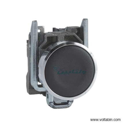
XB4BA31
- Quick and easy assembly and disassembly
- Robustness to withstand harsh environments
- Various types of connection: screw clamp, connector, Faston connector or spring terminal
- Excellent mechanical connection with operator head
- A wide choice of contact blocks for general purposes or specific applications (low current, standard)
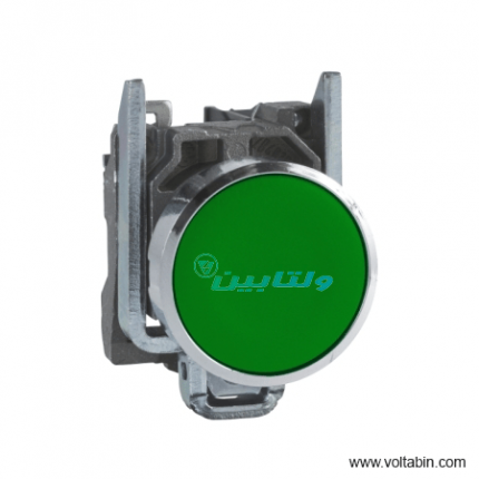
Range of product Harmony XB4 Product or component type Push-button Device short name XB4 Bezel material Chromium plated metal Fixing collar material Zamak Mounting diameter 22 mm Sale per indivisible quantity 1 Shape of signaling unit head Round Type of operator Spring return Operator profile Green flush, unmarked Head type Standard Contacts type and composition 1 NO Contact operation Slow-break Connections – terminals Screw clamp terminals, <= 2 x 1.5 mm² with cable end conforming to EN/IEC 60947-1
Screw clamp terminals, 1 x 0.22…2 x 2.5 mm² without cable end conforming to EN/IEC 60947-1Height 47 mm Width 30 mm Depth 52 mm Terminals description ISO n°1 (13-14)NO Net weight 0.08 kg Resistance to high pressure washer 7000000 Pa at 55 °C, distance : 0.1 m Contacts usage Standard contacts Positive opening Without Operating travel 2.6 mm (NO changing electrical state)
4.3 mm (total travel)Operating force 3.8 N NO changing electrical state Mechanical durability 10000000 cycles Tightening torque 0.8…1.2 N.m conforming to EN 60947-1 Shape of screw head Cross compatible with Philips no 1 screwdriver
Cross compatible with pozidriv No 1 screwdriver
Slotted compatible with flat Ø 4 mm screwdriver
Slotted compatible with flat Ø 5.5 mm screwdriverContacts material Silver alloy (Ag/Ni) Short-circuit protection 10 A cartridge fuse type gG conforming to EN/IEC 60947-5-1 [Ith] conventional free air thermal current 10 A conforming to EN/IEC 60947-5-1 [Ui] rated insulation voltage 600 V (pollution degree 3) conforming to EN/IEC 60947-1 [Uimp] rated impulse withstand voltage 6 kV conforming to EN/IEC 60947-1 [Ie] rated operational current 3 A at 240 V, AC-15, A600 conforming to EN/IEC 60947-5-1
6 A at 120 V, AC-15, A600 conforming to EN/IEC 60947-5-1
0.1 A at 600 V, DC-13, Q600 conforming to EN/IEC 60947-5-1
0.27 A at 250 V, DC-13, Q600 conforming to EN/IEC 60947-5-1
0.55 A at 125 V, DC-13, Q600 conforming to EN/IEC 60947-5-1
1.2 A at 600 V, AC-15, A600 conforming to EN/IEC 60947-5-1Electrical durability 1000000 cycles, AC-15, 2 A at 230 V, operating rate <3600 cyc/h, load factor: 0.5 conforming to EN/IEC 60947-5-1 appendix C
1000000 cycles, AC-15, 3 A at 120 V, operating rate <3600 cyc/h, load factor: 0.5 conforming to EN/IEC 60947-5-1 appendix C
1000000 cycles, AC-15, 4 A at 24 V, operating rate <3600 cyc/h, load factor: 0.5 conforming to EN/IEC 60947-5-1 appendix C
1000000 cycles, DC-13, 0.2 A at 110 V, operating rate <3600 cyc/h, load factor: 0.5 conforming to EN/IEC 60947-5-1 appendix C
1000000 cycles, DC-13, 0.5 A at 24 V, operating rate <3600 cyc/h, load factor: 0.5 conforming to EN/IEC 60947-5-1 appendix CElectrical reliability Λ < 10exp(-6) at 5 V and 1 mA in clean environment conforming to EN/IEC 60947-5-4
Λ < 10exp(-8) at 17 V and 5 mA in clean environment conforming to EN/IEC 60947-5-4Device presentation Complete product Protective treatment TH Ambient air temperature for storage -40…70 °C Ambient air temperature for operation -40…70 °C Overvoltage category Class I conforming to IEC 60536 IP degree of protection IP66 conforming to IEC 60529
IP67
IP69
IP69KNEMA degree of protection NEMA 13
NEMA 4XIK degree of protection IK06 conforming to IEC 50102 Standards JIS C8201-5-1
EN/IEC 60947-5-5
UL 508
EN/IEC 60947-1
EN/IEC 60947-5-4
EN/IEC 60947-5-1
CSA C22.2 No 14
JIS C8201-1Product certifications CSA
GL
BV
UL listed
DNV
LROS (Lloyds register of shipping)Vibration resistance 5 gn (f= 2…500 Hz) conforming to IEC 60068-2-6 Shock resistance 30 gn (duration = 18 ms) for half sine wave acceleration conforming to IEC 60068-2-27
50 gn (duration = 11 ms) for half sine wave acceleration conforming to IEC 60068-2-27Unit Type of Package 1 PCE Number of Units in Package 1 1 Package 1 Height 3.500 cm Package 1 Width 5.500 cm Package 1 Length 8.500 cm Package 1 Weight 78.800 g Unit Type of Package 2 S03 Number of Units in Package 2 150 Package 2 Height 30.000 cm Package 2 Width 30.000 cm Package 2 Length 40.000 cm Package 2 Weight 12.257 kg Unit Type of Package 3 P06 Number of Units in Package 3 1200 Package 3 Height 75.000 cm Package 3 Width 80.000 cm Package 3 Length 60.000 cm Package 3 Weight 106.056 kg
XB4BA3351
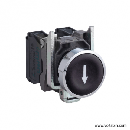
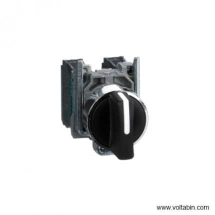
Range of product Harmony XB4 Product or component type Push-button device short name XB4 bezel material Chromium plated metal Fixing collar material Zamak Mounting diameter 22 mm Sale per indivisible quantity 1 Shape of signaling unit head Round Type of operator Spring return Operator profile Black flush, down arrow (white) Head type Standard contacts type and composition 1 NO contact operation Slow-break Connections – terminals Screw clamp terminals, <= 2 x 1.5 mm² with cable end conforming to EN/IEC 60947-1
Screw clamp terminals, 1 x 0.22…2 x 2.5 mm² without cable end conforming to EN/IEC 60947-1Net weight 0.08 kg Resistance to high pressure washer 7000000 Pa at 55 °C, distance : 0.1 m contacts usage Standard contacts Positive opening Without Operating travel 2.6 mm (NO changing electrical state)
4.3 mm (total travel)Operating force 3.8 N NO changing electrical state Mechanical durability 10000000 cycles Tightening torque 0.8…1.2 N.m conforming to EN 60947-1 Shape of screw head Cross compatible with Philips no 1 screwdriver
Cross compatible with pozidriv No 1 screwdriver
Slotted compatible with flat Ø 4 mm screwdriver
Slotted compatible with flat Ø 5.5 mm screwdrivercontacts material Silver alloy (Ag/Ni) Short-circuit protection 10 A cartridge fuse type gG conforming to EN/IEC 60947-5-1 [Ith] conventional free air thermal current 10 A conforming to EN/IEC 60947-5-1 [Ui] rated insulation voltage 600 V (pollution degree 3) conforming to EN/IEC 60947-1 [Uimp] rated impulse withstand voltage 6 kV conforming to EN/IEC 60947-1 [Ie] rated operational current 3 A at 240 V, AC-15, A600 conforming to EN/IEC 60947-5-1
6 A at 120 V, AC-15, A600 conforming to EN/IEC 60947-5-1
0.1 A at 600 V, DC-13, Q600 conforming to EN/IEC 60947-5-1
0.27 A at 250 V, DC-13, Q600 conforming to EN/IEC 60947-5-1
0.55 A at 125 V, DC-13, Q600 conforming to EN/IEC 60947-5-1
1.2 A at 600 V, AC-15, A600 conforming to EN/IEC 60947-5-1Electrical durability 1000000 cycles, AC-15, 2 A at 230 V, operating rate <3600 cyc/h, load factor: 0.5 conforming to EN/IEC 60947-5-1 appendix C
1000000 cycles, AC-15, 3 A at 120 V, operating rate <3600 cyc/h, load factor: 0.5 conforming to EN/IEC 60947-5-1 appendix C
1000000 cycles, AC-15, 4 A at 24 V, operating rate <3600 cyc/h, load factor: 0.5 conforming to EN/IEC 60947-5-1 appendix C
1000000 cycles, DC-13, 0.2 A at 110 V, operating rate <3600 cyc/h, load factor: 0.5 conforming to EN/IEC 60947-5-1 appendix C
1000000 cycles, DC-13, 0.5 A at 24 V, operating rate <3600 cyc/h, load factor: 0.5 conforming to EN/IEC 60947-5-1 appendix CElectrical reliability Λ < 10exp(-6) at 5 V and 1 mA in clean environment conforming to EN/IEC 60947-5-4
Λ < 10exp(-8) at 17 V and 5 mA in clean environment conforming to EN/IEC 60947-5-4device presentation Complete product Protective treatment TH Ambient air temperature for storage -40…70 °C Ambient air temperature for operation -40…70 °C Overvoltage category Class I conforming to IEC 60536 IP degree of protection IP66 conforming to IEC 60529
IP67
IP69
IP69KNEMA degree of protection NEMA 13
NEMA 4XIK degree of protection IK06 conforming to IEC 50102 Standards UL 508
EN/IEC 60947-1
EN/IEC 60947-5-5
EN/IEC 60947-5-4
CSA C22.2 No 14
EN/IEC 60947-5-1
JIS C8201-5-1
JIS C8201-1product certifications LROS (Lloyds register of shipping)
BV
CSA
GL
UL listed
DNVVibration resistance 5 gn (f= 2…500 Hz) conforming to IEC 60068-2-6 Shock resistance 30 gn (duration = 18 ms) for half sine wave acceleration conforming to IEC 60068-2-27
50 gn (duration = 11 ms) for half sine wave acceleration conforming to IEC 60068-2-27Unit Type of Package 1 PCE Number of Units in Package 1 1 Package 1 Height 8.800 cm Package 1 Width 3.400 cm Package 1 Length 5.400 cm Package 1 Weight 79.000 g Unit Type of Package 2 BB1 Number of Units in Package 2 5 Package 2 Height 8.800 cm Package 2 Width 3.400 cm Package 2 Length 26.500 cm Package 2 Weight 397.000 g Unit Type of Package 3 S03 Number of Units in Package 3 150 Package 3 Height 30 cm Package 3 Width 30 cm Package 3 Length 40 cm Package 3 Weight 12.386 kg
XB4BA42
range of product
Easy Altivar 610
product or component type
Variable speed drive
product specific application
Fan, pump, compressor, conveyor
device short name
ATV610
variant
Standard version
product destination
Asynchronous motors
mounting mode
Cabinet mount
EMC filter
Integrated conforming to EN/IEC 61800-3 category C3 with 50 m
IP degree of protection
IP20
type of cooling
Forced convection
supply frequency
50…60 Hz +/-5 %
network number of phases
3 phases
[Us] rated supply voltage
380…460 V – 15…10 %
motor power kW
110 kW for normal duty
90 kW for heavy duty
motor power hp
150 hp for normal duty
125 hp for heavy duty
line current
201 A at 380 V (normal duty)
175.7 A at 460 V (normal duty)
170 A at 380 V (heavy duty)
149.1 A at 460 V (heavy duty)
prospective line Isc
50 kA
apparent power
140.0 kVA at 460 V (normal duty)
118.8 kVA at 460 V (heavy duty)
continuous output current
211 A at 2.5 kHz for normal duty
173 A at 2.5 kHz for heavy duty
maximum transient current
232 A during 60 s (normal duty)
260 A during 60 s (heavy duty)
asynchronous motor control profile
Variable torque standard
Optimized torque mode
Constant torque standard
output frequency
0.0001…0.5 kHz
nominal switching frequency
2.5 kHz
switching frequency
1…8 kHz adjustable
number of preset speeds
16 preset speeds
communication port protocol
Modbus serial
option card
Slot A: communication card, Profibus DP V1
Slot A: digital or analog I/O extension card
Slot A: relay output card
output voltage
<= power supply voltage
motor slip compensation
Can be suppressed
Adjustable
Not available in permanent magnet motor law
Automatic whatever the load
acceleration and deceleration ramps
Linear adjustable separately from 0.01 to 9000 s
S, U or customized
braking to standstill
By DC injection
protection type
Thermal protection: motor
Motor phase break: motor
Thermal protection: drive
Overheating: drive
Overcurrent between output phases and earth: drive
Overload of output voltage: drive
Short-circuit protection: drive
Motor phase break: drive
Overvoltages on the DC bus: drive
Line supply overvoltage: drive
Line supply undervoltage: drive
Line supply phase loss: drive
Overspeed: drive
Break on the control circuit: drive
frequency resolution
Display unit: 0.1 Hz
Analog input: 0.012/50 Hz
electrical connection
Control, screw terminal: 0.5…1.5 mm²
Line side, screw terminal: 2 x 50…3 x 120 mm²
Motor, screw terminal: 3 x 50…3 x 120 mm²
connector type
1 RJ45 (on the remote graphic terminal) for Modbus serial
physical interface
2-wire RS 485 for Modbus serial
transmission frame
RTU for Modbus serial
transmission rate
4.8, 9.6, 19.2, 38.4 kbit/s for Modbus serial
type of polarization
No impedance for Modbus serial
number of addresses
1…247 for Modbus serial
method of access
Slave
supply
External supply for digital inputs: 24 V DC (19…30 V), <1.25 mA, protection type: overload and short-circuit protection
Internal supply for reference potentiometer (1 to 10 kOhm): 10.5 V DC +/- 5 %, <10 mA, protection type: overload and short-circuit protection
local signalling
2 LEDs for local diagnostic
1 LED (yellow) for embedded communication status
2 LEDs (dual colour) for communication module status
1 LED (red) for presence of voltage
width
320 mm
height
852 mm
1159 mm with IP21 conformity kit
depth
390 mm
net weight
82 kg
analogue input number
3
analogue input type
AI1, AI2, AI3 software-configurable voltage: 0…10 V DC, impedance: 30 kOhm, resolution 12 bits
AI1, AI2, AI3 software-configurable current: 0…20 mA, impedance: 250 Ohm, resolution 12 bits
AI2, AI3 software-configurable temperature probe or water level sensor
discrete input number
6
discrete input type
DI1…DI6 programmable as logic input, 24 V DC (<= 30 V), impedance: 3.5 kOhm
DI5, DI6 programmable as pulse input: 0…30 kHz, 24 V DC (<= 30 V)
input compatibility
DI1…DI6: logic input level 1 PLC conforming to EN/IEC 61131-2
DI5, DI6: pulse input level 1 PLC conforming to IEC 65A-68
discrete input logic
Positive logic (source): DI1…DI6 configurable logic input, < 5 V (state 0), > 11 V (state 1)
Negative logic (sink): DI1…DI6 configurable logic input, > 16 V (state 0), < 10 V (state 1)
Positive logic (source): DI5, DI6 configurable pulse input, < 0.6 V (state 0), > 2.5 V (state 1)
analogue output number
2
analogue output type
Software-configurable current AQ1, AQ2: 0…20 mA, resolution 10 bits
Software-configurable voltage AQ1, AQ2: 0…10 V DC impedance 470 Ohm, resolution 10 bits
sampling duration
5 ms +/- 0.1 ms (AI1, AI2, AI3) – analog input
2 ms +/- 0.5 ms (DI1…DI6)configurable – discrete input
5 ms +/- 1 ms (DI5, DI6)configurable – pulse input
10 ms +/- 1 ms (AQ1, AQ2) – analog output
accuracy
+/- 0.6 % AI1, AI2, AI3 for a temperature variation 60 °C analog input
+/- 1 % AQ1, AQ2 for a temperature variation 60 °C analog output
linearity error
AI1, AI2, AI3: +/- 0.15 % of maximum value for analog input
AQ1, AQ2: +/- 0.2 % for analog output
relay output number
3
relay output type
Configurable relay logic R1: fault relay NO/NC electrical durability 100000 cycles
Configurable relay logic R2: sequence relay NO electrical durability 100000 cycles
Configurable relay logic R3: sequence relay NO electrical durability 100000 cycles
refresh time
Relay output (R1, R2, R3): 5 ms (+/- 0.5 ms)
minimum switching current
Relay output R1, R2, R3: 5 mA at 24 V DC
maximum switching current
Relay output R1, R2, R3 on resistive load, cos phi = 1: 3 A at 250 V AC
Relay output R1, R2, R3 on resistive load, cos phi = 1: 3 A at 30 V DC
Relay output R1, R2, R3 on inductive load, cos phi = 0.4 and L/R = 7 ms: 2 A at 250 V AC
Relay output R1, R2, R3 on inductive load, cos phi = 0.4 and L/R = 7 ms: 2 A at 30 V DC
isolation
Between power and control terminals
insulation resistance
> 1 MOhm 500 V DC for 1 minute to earth
noise level
76 dB conforming to 86/188/EEC
power dissipation in W
2026 W(forced convection) at 380 V, switching frequency 2.5 kHz
operating position
Vertical +/- 10 degree
electromagnetic compatibility
Electrostatic discharge immunity test level 3 conforming to IEC 61000-4-2
Radiated radio-frequency electromagnetic field immunity test level 3 conforming to IEC 61000-4-3
Electrical fast transient/burst immunity test level 4 conforming to IEC 61000-4-4
1.2/50 µs – 8/20 µs surge immunity test level 3 conforming to IEC 61000-4-5
Conducted radio-frequency immunity test level 3 conforming to IEC 61000-4-6
pollution degree
2 conforming to EN/IEC 61800-5-1
vibration resistance
1.5 mm peak to peak (f= 2…13 Hz) conforming to IEC 60068-2-6
1 gn (f= 13…200 Hz) conforming to IEC 60068-2-6
shock resistance
6 gn for 11 ms conforming to IEC 60068-2-27
relative humidity
5…95 % without condensation conforming to IEC 60068-2-3
ambient air temperature for operation
-15…45 °C (without derating)
45…60 °C (with derating factor)
operating altitude
<= 1000 m without derating
1000…4800 m with current derating 1 % per 100 m
environmental characteristic
Chemical pollution resistance class 3C3 conforming to EN/IEC 60721-3-3
Dust pollution resistance class 3S3 conforming to EN/IEC 60721-3-3
standards
EN/IEC 61800-3
Environment 2 category C3 EN/IEC 61800-3
EN/IEC 61800-5-1
IEC 60721-3
marking
CE
Unit Type of Package 1
PCE
Number of Units in Package 1
1
Package 1 Weight
96.344 kg
Package 1 Height
47 cm
Package 1 width
67 cm
Package 1 Length
103 cm
XB4BA61
range of product
Easy Altivar 610
product or component type
Variable speed drive
product specific application
Fan, pump, compressor, conveyor
device short name
ATV610
variant
Standard version
product destination
Asynchronous motors
mounting mode
Cabinet mount
EMC filter
Integrated conforming to EN/IEC 61800-3 category C3 with 50 m
IP degree of protection
IP20
type of cooling
Forced convection
supply frequency
50…60 Hz +/-5 %
network number of phases
3 phases
[Us] rated supply voltage
380…460 V – 15…10 %
motor power kW
110 kW for normal duty
90 kW for heavy duty
motor power hp
150 hp for normal duty
125 hp for heavy duty
line current
201 A at 380 V (normal duty)
175.7 A at 460 V (normal duty)
170 A at 380 V (heavy duty)
149.1 A at 460 V (heavy duty)
prospective line Isc
50 kA
apparent power
140.0 kVA at 460 V (normal duty)
118.8 kVA at 460 V (heavy duty)
continuous output current
211 A at 2.5 kHz for normal duty
173 A at 2.5 kHz for heavy duty
maximum transient current
232 A during 60 s (normal duty)
260 A during 60 s (heavy duty)
asynchronous motor control profile
Variable torque standard
Optimized torque mode
Constant torque standard
output frequency
0.0001…0.5 kHz
nominal switching frequency
2.5 kHz
switching frequency
1…8 kHz adjustable
number of preset speeds
16 preset speeds
communication port protocol
Modbus serial
option card
Slot A: communication card, Profibus DP V1
Slot A: digital or analog I/O extension card
Slot A: relay output card
output voltage
<= power supply voltage
motor slip compensation
Can be suppressed
Adjustable
Not available in permanent magnet motor law
Automatic whatever the load
acceleration and deceleration ramps
Linear adjustable separately from 0.01 to 9000 s
S, U or customized
braking to standstill
By DC injection
protection type
Thermal protection: motor
Motor phase break: motor
Thermal protection: drive
Overheating: drive
Overcurrent between output phases and earth: drive
Overload of output voltage: drive
Short-circuit protection: drive
Motor phase break: drive
Overvoltages on the DC bus: drive
Line supply overvoltage: drive
Line supply undervoltage: drive
Line supply phase loss: drive
Overspeed: drive
Break on the control circuit: drive
frequency resolution
Display unit: 0.1 Hz
Analog input: 0.012/50 Hz
electrical connection
Control, screw terminal: 0.5…1.5 mm²
Line side, screw terminal: 2 x 50…3 x 120 mm²
Motor, screw terminal: 3 x 50…3 x 120 mm²
connector type
1 RJ45 (on the remote graphic terminal) for Modbus serial
physical interface
2-wire RS 485 for Modbus serial
transmission frame
RTU for Modbus serial
transmission rate
4.8, 9.6, 19.2, 38.4 kbit/s for Modbus serial
type of polarization
No impedance for Modbus serial
number of addresses
1…247 for Modbus serial
method of access
Slave
supply
External supply for digital inputs: 24 V DC (19…30 V), <1.25 mA, protection type: overload and short-circuit protection
Internal supply for reference potentiometer (1 to 10 kOhm): 10.5 V DC +/- 5 %, <10 mA, protection type: overload and short-circuit protection
local signalling
2 LEDs for local diagnostic
1 LED (yellow) for embedded communication status
2 LEDs (dual colour) for communication module status
1 LED (red) for presence of voltage
width
320 mm
height
852 mm
1159 mm with IP21 conformity kit
depth
390 mm
net weight
82 kg
analogue input number
3
analogue input type
AI1, AI2, AI3 software-configurable voltage: 0…10 V DC, impedance: 30 kOhm, resolution 12 bits
AI1, AI2, AI3 software-configurable current: 0…20 mA, impedance: 250 Ohm, resolution 12 bits
AI2, AI3 software-configurable temperature probe or water level sensor
discrete input number
6
discrete input type
DI1…DI6 programmable as logic input, 24 V DC (<= 30 V), impedance: 3.5 kOhm
DI5, DI6 programmable as pulse input: 0…30 kHz, 24 V DC (<= 30 V)
input compatibility
DI1…DI6: logic input level 1 PLC conforming to EN/IEC 61131-2
DI5, DI6: pulse input level 1 PLC conforming to IEC 65A-68
discrete input logic
Positive logic (source): DI1…DI6 configurable logic input, < 5 V (state 0), > 11 V (state 1)
Negative logic (sink): DI1…DI6 configurable logic input, > 16 V (state 0), < 10 V (state 1)
Positive logic (source): DI5, DI6 configurable pulse input, < 0.6 V (state 0), > 2.5 V (state 1)
analogue output number
2
analogue output type
Software-configurable current AQ1, AQ2: 0…20 mA, resolution 10 bits
Software-configurable voltage AQ1, AQ2: 0…10 V DC impedance 470 Ohm, resolution 10 bits
sampling duration
5 ms +/- 0.1 ms (AI1, AI2, AI3) – analog input
2 ms +/- 0.5 ms (DI1…DI6)configurable – discrete input
5 ms +/- 1 ms (DI5, DI6)configurable – pulse input
10 ms +/- 1 ms (AQ1, AQ2) – analog output
accuracy
+/- 0.6 % AI1, AI2, AI3 for a temperature variation 60 °C analog input
+/- 1 % AQ1, AQ2 for a temperature variation 60 °C analog output
linearity error
AI1, AI2, AI3: +/- 0.15 % of maximum value for analog input
AQ1, AQ2: +/- 0.2 % for analog output
relay output number
3
relay output type
Configurable relay logic R1: fault relay NO/NC electrical durability 100000 cycles
Configurable relay logic R2: sequence relay NO electrical durability 100000 cycles
Configurable relay logic R3: sequence relay NO electrical durability 100000 cycles
refresh time
Relay output (R1, R2, R3): 5 ms (+/- 0.5 ms)
minimum switching current
Relay output R1, R2, R3: 5 mA at 24 V DC
maximum switching current
Relay output R1, R2, R3 on resistive load, cos phi = 1: 3 A at 250 V AC
Relay output R1, R2, R3 on resistive load, cos phi = 1: 3 A at 30 V DC
Relay output R1, R2, R3 on inductive load, cos phi = 0.4 and L/R = 7 ms: 2 A at 250 V AC
Relay output R1, R2, R3 on inductive load, cos phi = 0.4 and L/R = 7 ms: 2 A at 30 V DC
isolation
Between power and control terminals
insulation resistance
> 1 MOhm 500 V DC for 1 minute to earth
noise level
76 dB conforming to 86/188/EEC
power dissipation in W
2026 W(forced convection) at 380 V, switching frequency 2.5 kHz
operating position
Vertical +/- 10 degree
electromagnetic compatibility
Electrostatic discharge immunity test level 3 conforming to IEC 61000-4-2
Radiated radio-frequency electromagnetic field immunity test level 3 conforming to IEC 61000-4-3
Electrical fast transient/burst immunity test level 4 conforming to IEC 61000-4-4
1.2/50 µs – 8/20 µs surge immunity test level 3 conforming to IEC 61000-4-5
Conducted radio-frequency immunity test level 3 conforming to IEC 61000-4-6
pollution degree
2 conforming to EN/IEC 61800-5-1
vibration resistance
1.5 mm peak to peak (f= 2…13 Hz) conforming to IEC 60068-2-6
1 gn (f= 13…200 Hz) conforming to IEC 60068-2-6
shock resistance
6 gn for 11 ms conforming to IEC 60068-2-27
relative humidity
5…95 % without condensation conforming to IEC 60068-2-3
ambient air temperature for operation
-15…45 °C (without derating)
45…60 °C (with derating factor)
operating altitude
<= 1000 m without derating
1000…4800 m with current derating 1 % per 100 m
environmental characteristic
Chemical pollution resistance class 3C3 conforming to EN/IEC 60721-3-3
Dust pollution resistance class 3S3 conforming to EN/IEC 60721-3-3
standards
EN/IEC 61800-3
Environment 2 category C3 EN/IEC 61800-3
EN/IEC 61800-5-1
IEC 60721-3
marking
CE
Unit Type of Package 1
PCE
Number of Units in Package 1
1
Package 1 Weight
96.344 kg
Package 1 Height
47 cm
Package 1 width
67 cm
Package 1 Length
103 cm
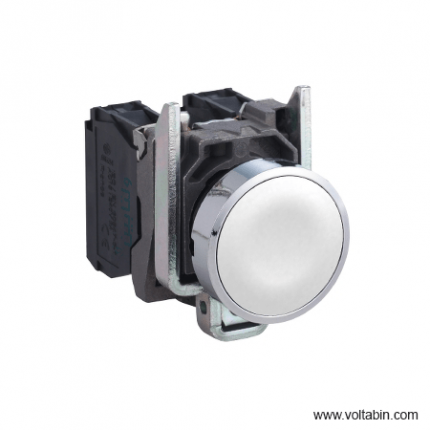
XB4BACUST01
Range of product Harmony XB4 Product or component type Push-button device short name XB4 Bezel material Chromium plated metal Fixing collar material Zamak Mounting diameter 22 mm Sale per indivisible quantity 1 Shape of signaling unit head Round Type of operator Spring return Operator profile White flush, unmarked Head type Standard Contacts type and composition 1 NO Contact operation Slow-break Connections – terminals Screw clamp terminals, <= 2 x 1.5 mm² with cable end conforming to EN/IEC 60947-1
Screw clamp terminals, 1 x 0.22…2 x 2.5 mm² without cable end conforming to EN/IEC 60947-1Height 47 mm Width 30 mm Depth 52 mm Terminals description ISO n°1 (13-14)NO Product weight 0.08 kg Resistance to high pressure washer 7000000 Pa at 55 °C, distance : 0.1 m Contacts usage Standard contacts Positive opening Without Operating travel 2.6 mm (NO changing electrical state)
4.3 mm (total travel)Operating force 3.8 N NO changing electrical state Mechanical durability 10000000 cycles Tightening torque 0.8…1.2 N.m conforming to EN 60947-1 Shape of screw head Cross compatible with Philips no 1 screwdriver
Cross compatible with pozidriv No 1 screwdriver
Slotted compatible with flat Ø 4 mm screwdriver
Slotted compatible with flat Ø 5.5 mm screwdriverContacts material Silver alloy (Ag/Ni) Short-circuit protection 10 A cartridge fuse type gG conforming to EN/IEC 60947-5-1 [Ith] conventional free air thermal current 10 A conforming to EN/IEC 60947-5-1 [Ui] rated insulation voltage 600 V (pollution degree 3) conforming to EN/IEC 60947-1 [Uimp] rated impulse withstand voltage 6 kV conforming to EN/IEC 60947-1 [Ie] rated operational current 3 A at 240 V, AC-15, A600 conforming to EN/IEC 60947-5-1
6 A at 120 V, AC-15, A600 conforming to EN/IEC 60947-5-1
0.1 A at 600 V, DC-13, Q600 conforming to EN/IEC 60947-5-1
0.27 A at 250 V, DC-13, Q600 conforming to EN/IEC 60947-5-1
0.55 A at 125 V, DC-13, Q600 conforming to EN/IEC 60947-5-1
1.2 A at 600 V, AC-15, A600 conforming to EN/IEC 60947-5-1Electrical durability 1000000 cycles, AC-15, 2 A at 230 V, operating rate <3600 cyc/h, load factor: 0.5 conforming to EN/IEC 60947-5-1 appendix C
1000000 cycles, AC-15, 3 A at 120 V, operating rate <3600 cyc/h, load factor: 0.5 conforming to EN/IEC 60947-5-1 appendix C
1000000 cycles, AC-15, 4 A at 24 V, operating rate <3600 cyc/h, load factor: 0.5 conforming to EN/IEC 60947-5-1 appendix C
1000000 cycles, DC-13, 0.2 A at 110 V, operating rate <3600 cyc/h, load factor: 0.5 conforming to EN/IEC 60947-5-1 appendix C
1000000 cycles, DC-13, 0.5 A at 24 V, operating rate <3600 cyc/h, load factor: 0.5 conforming to EN/IEC 60947-5-1 appendix CElectrical reliability Λ < 10exp(-6) at 5 V and 1 mA in clean environment conforming to EN/IEC 60947-5-4
Λ < 10exp(-8) at 17 V and 5 mA in clean environment conforming to EN/IEC 60947-5-4Device presentation Complete product Protective treatment TH Ambient air temperature for storage -40…70 °C Ambient air temperature for operation -40…70 °C Overvoltage category Class I conforming to IEC 60536 IP degree of protection IP66 conforming to IEC 60529
IP67
IP69
IP69KNEMA degree of protection NEMA 13
NEMA 4XIK degree of protection IK06 conforming to IEC 50102 Standards CSA C22.2 No 14
EN/IEC 60947-5-1
EN/IEC 60947-5-4
UL 508
EN/IEC 60947-5-5
EN/IEC 60947-1
JIS C8201-5-1
JIS C8201-1Product certifications BV
UL listed
CSA
GL
DNV
LROS (Lloyds register of shipping)Vibration resistance 5 gn (f= 2…500 Hz) conforming to IEC 60068-2-6 Shock resistance 30 gn (duration = 18 ms) for half sine wave acceleration conforming to IEC 60068-2-27
50 gn (duration = 11 ms) for half sine wave acceleration conforming to IEC 60068-2-27Unit Type of Package 1 PCE Number of Units in Package 1 1 Package 1 Height 3.5 cm Package 1 Width 5.4 cm Package 1 Length 8.8 cm Package 1 Weight 79.0 g
XB4BD33
range of product
Easy Altivar 610
product or component type
Variable speed drive
product specific application
Fan, pump, compressor, conveyor
device short name
ATV610
variant
Standard version
product destination
Asynchronous motors
mounting mode
Cabinet mount
EMC filter
Integrated conforming to EN/IEC 61800-3 category C3 with 50 m
IP degree of protection
IP20
type of cooling
Forced convection
supply frequency
50…60 Hz +/-5 %
network number of phases
3 phases
[Us] rated supply voltage
380…460 V – 15…10 %
motor power kW
110 kW for normal duty
90 kW for heavy duty
motor power hp
150 hp for normal duty
125 hp for heavy duty
line current
201 A at 380 V (normal duty)
175.7 A at 460 V (normal duty)
170 A at 380 V (heavy duty)
149.1 A at 460 V (heavy duty)
prospective line Isc
50 kA
apparent power
140.0 kVA at 460 V (normal duty)
118.8 kVA at 460 V (heavy duty)
continuous output current
211 A at 2.5 kHz for normal duty
173 A at 2.5 kHz for heavy duty
maximum transient current
232 A during 60 s (normal duty)
260 A during 60 s (heavy duty)
asynchronous motor control profile
Variable torque standard
Optimized torque mode
Constant torque standard
output frequency
0.0001…0.5 kHz
nominal switching frequency
2.5 kHz
switching frequency
1…8 kHz adjustable
number of preset speeds
16 preset speeds
communication port protocol
Modbus serial
option card
Slot A: communication card, Profibus DP V1
Slot A: digital or analog I/O extension card
Slot A: relay output card
output voltage
<= power supply voltage
motor slip compensation
Can be suppressed
Adjustable
Not available in permanent magnet motor law
Automatic whatever the load
acceleration and deceleration ramps
Linear adjustable separately from 0.01 to 9000 s
S, U or customized
braking to standstill
By DC injection
protection type
Thermal protection: motor
Motor phase break: motor
Thermal protection: drive
Overheating: drive
Overcurrent between output phases and earth: drive
Overload of output voltage: drive
Short-circuit protection: drive
Motor phase break: drive
Overvoltages on the DC bus: drive
Line supply overvoltage: drive
Line supply undervoltage: drive
Line supply phase loss: drive
Overspeed: drive
Break on the control circuit: drive
frequency resolution
Display unit: 0.1 Hz
Analog input: 0.012/50 Hz
electrical connection
Control, screw terminal: 0.5…1.5 mm²
Line side, screw terminal: 2 x 50…3 x 120 mm²
Motor, screw terminal: 3 x 50…3 x 120 mm²
connector type
1 RJ45 (on the remote graphic terminal) for Modbus serial
physical interface
2-wire RS 485 for Modbus serial
transmission frame
RTU for Modbus serial
transmission rate
4.8, 9.6, 19.2, 38.4 kbit/s for Modbus serial
type of polarization
No impedance for Modbus serial
number of addresses
1…247 for Modbus serial
method of access
Slave
supply
External supply for digital inputs: 24 V DC (19…30 V), <1.25 mA, protection type: overload and short-circuit protection
Internal supply for reference potentiometer (1 to 10 kOhm): 10.5 V DC +/- 5 %, <10 mA, protection type: overload and short-circuit protection
local signalling
2 LEDs for local diagnostic
1 LED (yellow) for embedded communication status
2 LEDs (dual colour) for communication module status
1 LED (red) for presence of voltage
width
320 mm
height
852 mm
1159 mm with IP21 conformity kit
depth
390 mm
net weight
82 kg
analogue input number
3
analogue input type
AI1, AI2, AI3 software-configurable voltage: 0…10 V DC, impedance: 30 kOhm, resolution 12 bits
AI1, AI2, AI3 software-configurable current: 0…20 mA, impedance: 250 Ohm, resolution 12 bits
AI2, AI3 software-configurable temperature probe or water level sensor
discrete input number
6
discrete input type
DI1…DI6 programmable as logic input, 24 V DC (<= 30 V), impedance: 3.5 kOhm
DI5, DI6 programmable as pulse input: 0…30 kHz, 24 V DC (<= 30 V)
input compatibility
DI1…DI6: logic input level 1 PLC conforming to EN/IEC 61131-2
DI5, DI6: pulse input level 1 PLC conforming to IEC 65A-68
discrete input logic
Positive logic (source): DI1…DI6 configurable logic input, < 5 V (state 0), > 11 V (state 1)
Negative logic (sink): DI1…DI6 configurable logic input, > 16 V (state 0), < 10 V (state 1)
Positive logic (source): DI5, DI6 configurable pulse input, < 0.6 V (state 0), > 2.5 V (state 1)
analogue output number
2
analogue output type
Software-configurable current AQ1, AQ2: 0…20 mA, resolution 10 bits
Software-configurable voltage AQ1, AQ2: 0…10 V DC impedance 470 Ohm, resolution 10 bits
sampling duration
5 ms +/- 0.1 ms (AI1, AI2, AI3) – analog input
2 ms +/- 0.5 ms (DI1…DI6)configurable – discrete input
5 ms +/- 1 ms (DI5, DI6)configurable – pulse input
10 ms +/- 1 ms (AQ1, AQ2) – analog output
accuracy
+/- 0.6 % AI1, AI2, AI3 for a temperature variation 60 °C analog input
+/- 1 % AQ1, AQ2 for a temperature variation 60 °C analog output
linearity error
AI1, AI2, AI3: +/- 0.15 % of maximum value for analog input
AQ1, AQ2: +/- 0.2 % for analog output
relay output number
3
relay output type
Configurable relay logic R1: fault relay NO/NC electrical durability 100000 cycles
Configurable relay logic R2: sequence relay NO electrical durability 100000 cycles
Configurable relay logic R3: sequence relay NO electrical durability 100000 cycles
refresh time
Relay output (R1, R2, R3): 5 ms (+/- 0.5 ms)
minimum switching current
Relay output R1, R2, R3: 5 mA at 24 V DC
maximum switching current
Relay output R1, R2, R3 on resistive load, cos phi = 1: 3 A at 250 V AC
Relay output R1, R2, R3 on resistive load, cos phi = 1: 3 A at 30 V DC
Relay output R1, R2, R3 on inductive load, cos phi = 0.4 and L/R = 7 ms: 2 A at 250 V AC
Relay output R1, R2, R3 on inductive load, cos phi = 0.4 and L/R = 7 ms: 2 A at 30 V DC
isolation
Between power and control terminals
insulation resistance
> 1 MOhm 500 V DC for 1 minute to earth
noise level
76 dB conforming to 86/188/EEC
power dissipation in W
2026 W(forced convection) at 380 V, switching frequency 2.5 kHz
operating position
Vertical +/- 10 degree
electromagnetic compatibility
Electrostatic discharge immunity test level 3 conforming to IEC 61000-4-2
Radiated radio-frequency electromagnetic field immunity test level 3 conforming to IEC 61000-4-3
Electrical fast transient/burst immunity test level 4 conforming to IEC 61000-4-4
1.2/50 µs – 8/20 µs surge immunity test level 3 conforming to IEC 61000-4-5
Conducted radio-frequency immunity test level 3 conforming to IEC 61000-4-6
pollution degree
2 conforming to EN/IEC 61800-5-1
vibration resistance
1.5 mm peak to peak (f= 2…13 Hz) conforming to IEC 60068-2-6
1 gn (f= 13…200 Hz) conforming to IEC 60068-2-6
shock resistance
6 gn for 11 ms conforming to IEC 60068-2-27
relative humidity
5…95 % without condensation conforming to IEC 60068-2-3
ambient air temperature for operation
-15…45 °C (without derating)
45…60 °C (with derating factor)
operating altitude
<= 1000 m without derating
1000…4800 m with current derating 1 % per 100 m
environmental characteristic
Chemical pollution resistance class 3C3 conforming to EN/IEC 60721-3-3
Dust pollution resistance class 3S3 conforming to EN/IEC 60721-3-3
standards
EN/IEC 61800-3
Environment 2 category C3 EN/IEC 61800-3
EN/IEC 61800-5-1
IEC 60721-3
marking
CE
Unit Type of Package 1
PCE
Number of Units in Package 1
1
Package 1 Weight
96.344 kg
Package 1 Height
47 cm
Package 1 width
67 cm
Package 1 Length
103 cm
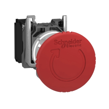
XB4BS8442
| Range of product | Harmony XB4 |
|---|---|
| Product or component type | Emergency switching off push-button Emergency stop push-button |
| Device short name | XB4 |
| Bezel material | Chromium plated metal |
| Fixing collar material | Zamak |
| Mounting diameter | 22 mm |
| Sale per indivisible quantity | 1 |
| Shape of signaling unit head | Round |
| Type of operator | Trigger action and mechanical latching |
| Head type | Standard |
| reset | Turn to release |
| Operator profile | Red mushroom Ø 40 mm, unmarked |
| Contact operation | Slow-break |
| Connections - terminals | Screw clamp terminals, <= 2 x 1.5 mm² with cable end conforming to EN 60947-1 Screw clamp terminals, >= 1 x 0.22 mm² without cable end conforming to EN 60947-1 |
| Height | 47 mm |
|---|---|
| Width | 40 mm |
| Depth | 82 mm |
| Terminals description ISO n°1 | (21-22)NC |
| Net weight | 0.118 kg |
| Resistance to high pressure washer | 7000000 Pa at 55 °C, distance : 0.1 m |
| Contacts usage | Standard contacts |
| Positive opening | With conforming to EN/IEC 60947-5-1 appendix K |
| Operating travel | 1.5 mm (NC changing electrical state) 4.3 mm (total travel) |
| Mechanical durability | 300000 cycles |
| Tightening torque | 0.8…1.2 N.m conforming to EN 60947-1 |
| Shape of screw head | Cross compatible with Philips no 1 screwdriver Cross compatible with pozidriv No 1 screwdriver Slotted compatible with flat Ø 4 mm screwdriver Slotted compatible with flat Ø 5.5 mm screwdriver |
| Contacts material | Silver alloy (Ag/Ni) |
| Short-circuit protection | 10 A cartridge fuse type gG conforming to EN/IEC 60947-5-1 |
| [Ith] conventional free air thermal current | 10 A conforming to EN/IEC 60947-5-1 |
| [Ui] rated insulation voltage | 600 V (pollution degree 3) conforming to EN 60947-1 |
| [Uimp] rated impulse withstand voltage | 6 kV conforming to EN 60947-1 |
| [Ie] rated operational current | 3 A at 240 V, AC-15, A600 conforming to EN/IEC 60947-5-1 6 A at 120 V, AC-15, A600 conforming to EN/IEC 60947-5-1 0.1 A at 600 V, DC-13, Q600 conforming to EN/IEC 60947-5-1 0.27 A at 250 V, DC-13, Q600 conforming to EN/IEC 60947-5-1 0.55 A at 125 V, DC-13, Q600 conforming to EN/IEC 60947-5-1 1.2 A at 600 V, AC-15, A600 conforming to EN/IEC 60947-5-1 |
| Electrical durability | 1000000 cycles, AC-15, 2 A at 230 V, operating rate <3600 cyc/h, load factor: 0.5 conforming to EN/IEC 60947-5-1 appendix C 1000000 cycles, AC-15, 3 A at 120 V, operating rate <3600 cyc/h, load factor: 0.5 conforming to EN/IEC 60947-5-1 appendix C 1000000 cycles, AC-15, 4 A at 24 V, operating rate <3600 cyc/h, load factor: 0.5 conforming to EN/IEC 60947-5-1 appendix C 1000000 cycles, DC-13, 0.2 A at 110 V, operating rate <3600 cyc/h, load factor: 0.5 conforming to EN/IEC 60947-5-1 appendix C 1000000 cycles, DC-13, 0.5 A at 24 V, operating rate <3600 cyc/h, load factor: 0.5 conforming to EN/IEC 60947-5-1 appendix C |
| Electrical reliability | Λ < 10exp(-6) at 5 V and 1 mA in clean environment conforming to EN/IEC 60947-5-4 Λ < 10exp(-8) at 17 V and 5 mA in clean environment conforming to EN/IEC 60947-5-4 |
| Device presentation | Complete product |
| Protective treatment | TH |
|---|---|
| Ambient air temperature for storage | -40…70 °C |
| Ambient air temperature for operation | -40…70 °C |
| Electrical shock protection class | Class I conforming to IEC 60536 |
| IP degree of protection | IP66 conforming to IEC 60529 IP67 IP69 IP69K |
| NEMA degree of protection | NEMA 13 NEMA 4X |
| IK degree of protection | IK06 conforming to IEC 50102 |
| Standards | EN/IEC 60947-5-1 UL 508 CSA C22.2 No 14 EN/ISO 13850 EN/IEC 60947-5-5 JIS C8201-5-1 EN/IEC 60947-1 EN/IEC 60947-5-4 EN/IEC 60204-1 IEC 60364-5-53 JIS C8201-1 |
| Product certifications | CSA BV UL listed LROS (Lloyds register of shipping) GL DNV |
| Vibration resistance | 5 gn (f= 2…500 Hz) conforming to IEC 60068-2-6 |
| Shock resistance | 30 gn (duration = 18 ms) for half sine wave acceleration conforming to IEC 60068-2-27 50 gn (duration = 11 ms) for half sine wave acceleration conforming to IEC 60068-2-27 |
| Unit Type of Package 1 | PCE |
|---|---|
| Number of Units in Package 1 | 1 |
| Package 1 Height | 4.500 cm |
| Package 1 Width | 5.500 cm |
| Package 1 Length | 9.000 cm |
| Package 1 Weight | 124.300 g |
| Unit Type of Package 2 | S03 |
| Number of Units in Package 2 | 80 |
| Package 2 Height | 30.000 cm |
| Package 2 Width | 30.000 cm |
| Package 2 Length | 40.000 cm |
| Package 2 Weight | 10.369 kg |
| Unit Type of Package 3 | P06 |
| Number of Units in Package 3 | 640 |
| Package 3 Height | 75.000 cm |
| Package 3 Width | 80.000 cm |
| Package 3 Length | 60.000 cm |
| Package 3 Weight | 90.949 kg |
XB4BVM3
range of product
Easy Altivar 610
product or component type
Variable speed drive
product specific application
Fan, pump, compressor, conveyor
device short name
ATV610
variant
Standard version
product destination
Asynchronous motors
mounting mode
Cabinet mount
EMC filter
Integrated conforming to EN/IEC 61800-3 category C3 with 50 m
IP degree of protection
IP20
type of cooling
Forced convection
supply frequency
50…60 Hz +/-5 %
network number of phases
3 phases
[Us] rated supply voltage
380…460 V – 15…10 %
motor power kW
110 kW for normal duty
90 kW for heavy duty
motor power hp
150 hp for normal duty
125 hp for heavy duty
line current
201 A at 380 V (normal duty)
175.7 A at 460 V (normal duty)
170 A at 380 V (heavy duty)
149.1 A at 460 V (heavy duty)
prospective line Isc
50 kA
apparent power
140.0 kVA at 460 V (normal duty)
118.8 kVA at 460 V (heavy duty)
continuous output current
211 A at 2.5 kHz for normal duty
173 A at 2.5 kHz for heavy duty
maximum transient current
232 A during 60 s (normal duty)
260 A during 60 s (heavy duty)
asynchronous motor control profile
Variable torque standard
Optimized torque mode
Constant torque standard
output frequency
0.0001…0.5 kHz
nominal switching frequency
2.5 kHz
switching frequency
1…8 kHz adjustable
number of preset speeds
16 preset speeds
communication port protocol
Modbus serial
option card
Slot A: communication card, Profibus DP V1
Slot A: digital or analog I/O extension card
Slot A: relay output card
output voltage
<= power supply voltage
motor slip compensation
Can be suppressed
Adjustable
Not available in permanent magnet motor law
Automatic whatever the load
acceleration and deceleration ramps
Linear adjustable separately from 0.01 to 9000 s
S, U or customized
braking to standstill
By DC injection
protection type
Thermal protection: motor
Motor phase break: motor
Thermal protection: drive
Overheating: drive
Overcurrent between output phases and earth: drive
Overload of output voltage: drive
Short-circuit protection: drive
Motor phase break: drive
Overvoltages on the DC bus: drive
Line supply overvoltage: drive
Line supply undervoltage: drive
Line supply phase loss: drive
Overspeed: drive
Break on the control circuit: drive
frequency resolution
Display unit: 0.1 Hz
Analog input: 0.012/50 Hz
electrical connection
Control, screw terminal: 0.5…1.5 mm²
Line side, screw terminal: 2 x 50…3 x 120 mm²
Motor, screw terminal: 3 x 50…3 x 120 mm²
connector type
1 RJ45 (on the remote graphic terminal) for Modbus serial
physical interface
2-wire RS 485 for Modbus serial
transmission frame
RTU for Modbus serial
transmission rate
4.8, 9.6, 19.2, 38.4 kbit/s for Modbus serial
type of polarization
No impedance for Modbus serial
number of addresses
1…247 for Modbus serial
method of access
Slave
supply
External supply for digital inputs: 24 V DC (19…30 V), <1.25 mA, protection type: overload and short-circuit protection
Internal supply for reference potentiometer (1 to 10 kOhm): 10.5 V DC +/- 5 %, <10 mA, protection type: overload and short-circuit protection
local signalling
2 LEDs for local diagnostic
1 LED (yellow) for embedded communication status
2 LEDs (dual colour) for communication module status
1 LED (red) for presence of voltage
width
320 mm
height
852 mm
1159 mm with IP21 conformity kit
depth
390 mm
net weight
82 kg
analogue input number
3
analogue input type
AI1, AI2, AI3 software-configurable voltage: 0…10 V DC, impedance: 30 kOhm, resolution 12 bits
AI1, AI2, AI3 software-configurable current: 0…20 mA, impedance: 250 Ohm, resolution 12 bits
AI2, AI3 software-configurable temperature probe or water level sensor
discrete input number
6
discrete input type
DI1…DI6 programmable as logic input, 24 V DC (<= 30 V), impedance: 3.5 kOhm
DI5, DI6 programmable as pulse input: 0…30 kHz, 24 V DC (<= 30 V)
input compatibility
DI1…DI6: logic input level 1 PLC conforming to EN/IEC 61131-2
DI5, DI6: pulse input level 1 PLC conforming to IEC 65A-68
discrete input logic
Positive logic (source): DI1…DI6 configurable logic input, < 5 V (state 0), > 11 V (state 1)
Negative logic (sink): DI1…DI6 configurable logic input, > 16 V (state 0), < 10 V (state 1)
Positive logic (source): DI5, DI6 configurable pulse input, < 0.6 V (state 0), > 2.5 V (state 1)
analogue output number
2
analogue output type
Software-configurable current AQ1, AQ2: 0…20 mA, resolution 10 bits
Software-configurable voltage AQ1, AQ2: 0…10 V DC impedance 470 Ohm, resolution 10 bits
sampling duration
5 ms +/- 0.1 ms (AI1, AI2, AI3) – analog input
2 ms +/- 0.5 ms (DI1…DI6)configurable – discrete input
5 ms +/- 1 ms (DI5, DI6)configurable – pulse input
10 ms +/- 1 ms (AQ1, AQ2) – analog output
accuracy
+/- 0.6 % AI1, AI2, AI3 for a temperature variation 60 °C analog input
+/- 1 % AQ1, AQ2 for a temperature variation 60 °C analog output
linearity error
AI1, AI2, AI3: +/- 0.15 % of maximum value for analog input
AQ1, AQ2: +/- 0.2 % for analog output
relay output number
3
relay output type
Configurable relay logic R1: fault relay NO/NC electrical durability 100000 cycles
Configurable relay logic R2: sequence relay NO electrical durability 100000 cycles
Configurable relay logic R3: sequence relay NO electrical durability 100000 cycles
refresh time
Relay output (R1, R2, R3): 5 ms (+/- 0.5 ms)
minimum switching current
Relay output R1, R2, R3: 5 mA at 24 V DC
maximum switching current
Relay output R1, R2, R3 on resistive load, cos phi = 1: 3 A at 250 V AC
Relay output R1, R2, R3 on resistive load, cos phi = 1: 3 A at 30 V DC
Relay output R1, R2, R3 on inductive load, cos phi = 0.4 and L/R = 7 ms: 2 A at 250 V AC
Relay output R1, R2, R3 on inductive load, cos phi = 0.4 and L/R = 7 ms: 2 A at 30 V DC
isolation
Between power and control terminals
insulation resistance
> 1 MOhm 500 V DC for 1 minute to earth
noise level
76 dB conforming to 86/188/EEC
power dissipation in W
2026 W(forced convection) at 380 V, switching frequency 2.5 kHz
operating position
Vertical +/- 10 degree
electromagnetic compatibility
Electrostatic discharge immunity test level 3 conforming to IEC 61000-4-2
Radiated radio-frequency electromagnetic field immunity test level 3 conforming to IEC 61000-4-3
Electrical fast transient/burst immunity test level 4 conforming to IEC 61000-4-4
1.2/50 µs – 8/20 µs surge immunity test level 3 conforming to IEC 61000-4-5
Conducted radio-frequency immunity test level 3 conforming to IEC 61000-4-6
pollution degree
2 conforming to EN/IEC 61800-5-1
vibration resistance
1.5 mm peak to peak (f= 2…13 Hz) conforming to IEC 60068-2-6
1 gn (f= 13…200 Hz) conforming to IEC 60068-2-6
shock resistance
6 gn for 11 ms conforming to IEC 60068-2-27
relative humidity
5…95 % without condensation conforming to IEC 60068-2-3
ambient air temperature for operation
-15…45 °C (without derating)
45…60 °C (with derating factor)
operating altitude
<= 1000 m without derating
1000…4800 m with current derating 1 % per 100 m
environmental characteristic
Chemical pollution resistance class 3C3 conforming to EN/IEC 60721-3-3
Dust pollution resistance class 3S3 conforming to EN/IEC 60721-3-3
standards
EN/IEC 61800-3
Environment 2 category C3 EN/IEC 61800-3
EN/IEC 61800-5-1
IEC 60721-3
marking
CE
Unit Type of Package 1
PCE
Number of Units in Package 1
1
Package 1 Weight
96.344 kg
Package 1 Height
47 cm
Package 1 width
67 cm
Package 1 Length
103 cm
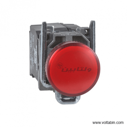
XB4BVM4
range of product
Easy Altivar 610
product or component type
Variable speed drive
product specific application
Fan, pump, compressor, conveyor
device short name
ATV610
variant
Standard version
product destination
Asynchronous motors
mounting mode
Cabinet mount
EMC filter
Integrated conforming to EN/IEC 61800-3 category C3 with 50 m
IP degree of protection
IP20
type of cooling
Forced convection
supply frequency
50…60 Hz +/-5 %
network number of phases
3 phases
[Us] rated supply voltage
380…460 V – 15…10 %
motor power kW
110 kW for normal duty
90 kW for heavy duty
motor power hp
150 hp for normal duty
125 hp for heavy duty
line current
201 A at 380 V (normal duty)
175.7 A at 460 V (normal duty)
170 A at 380 V (heavy duty)
149.1 A at 460 V (heavy duty)
prospective line Isc
50 kA
apparent power
140.0 kVA at 460 V (normal duty)
118.8 kVA at 460 V (heavy duty)
continuous output current
211 A at 2.5 kHz for normal duty
173 A at 2.5 kHz for heavy duty
maximum transient current
232 A during 60 s (normal duty)
260 A during 60 s (heavy duty)
asynchronous motor control profile
Variable torque standard
Optimized torque mode
Constant torque standard
output frequency
0.0001…0.5 kHz
nominal switching frequency
2.5 kHz
switching frequency
1…8 kHz adjustable
number of preset speeds
16 preset speeds
communication port protocol
Modbus serial
option card
Slot A: communication card, Profibus DP V1
Slot A: digital or analog I/O extension card
Slot A: relay output card
output voltage
<= power supply voltage
motor slip compensation
Can be suppressed
Adjustable
Not available in permanent magnet motor law
Automatic whatever the load
acceleration and deceleration ramps
Linear adjustable separately from 0.01 to 9000 s
S, U or customized
braking to standstill
By DC injection
protection type
Thermal protection: motor
Motor phase break: motor
Thermal protection: drive
Overheating: drive
Overcurrent between output phases and earth: drive
Overload of output voltage: drive
Short-circuit protection: drive
Motor phase break: drive
Overvoltages on the DC bus: drive
Line supply overvoltage: drive
Line supply undervoltage: drive
Line supply phase loss: drive
Overspeed: drive
Break on the control circuit: drive
frequency resolution
Display unit: 0.1 Hz
Analog input: 0.012/50 Hz
electrical connection
Control, screw terminal: 0.5…1.5 mm²
Line side, screw terminal: 2 x 50…3 x 120 mm²
Motor, screw terminal: 3 x 50…3 x 120 mm²
connector type
1 RJ45 (on the remote graphic terminal) for Modbus serial
physical interface
2-wire RS 485 for Modbus serial
transmission frame
RTU for Modbus serial
transmission rate
4.8, 9.6, 19.2, 38.4 kbit/s for Modbus serial
type of polarization
No impedance for Modbus serial
number of addresses
1…247 for Modbus serial
method of access
Slave
supply
External supply for digital inputs: 24 V DC (19…30 V), <1.25 mA, protection type: overload and short-circuit protection
Internal supply for reference potentiometer (1 to 10 kOhm): 10.5 V DC +/- 5 %, <10 mA, protection type: overload and short-circuit protection
local signalling
2 LEDs for local diagnostic
1 LED (yellow) for embedded communication status
2 LEDs (dual colour) for communication module status
1 LED (red) for presence of voltage
width
320 mm
height
852 mm
1159 mm with IP21 conformity kit
depth
390 mm
net weight
82 kg
analogue input number
3
analogue input type
AI1, AI2, AI3 software-configurable voltage: 0…10 V DC, impedance: 30 kOhm, resolution 12 bits
AI1, AI2, AI3 software-configurable current: 0…20 mA, impedance: 250 Ohm, resolution 12 bits
AI2, AI3 software-configurable temperature probe or water level sensor
discrete input number
6
discrete input type
DI1…DI6 programmable as logic input, 24 V DC (<= 30 V), impedance: 3.5 kOhm
DI5, DI6 programmable as pulse input: 0…30 kHz, 24 V DC (<= 30 V)
input compatibility
DI1…DI6: logic input level 1 PLC conforming to EN/IEC 61131-2
DI5, DI6: pulse input level 1 PLC conforming to IEC 65A-68
discrete input logic
Positive logic (source): DI1…DI6 configurable logic input, < 5 V (state 0), > 11 V (state 1)
Negative logic (sink): DI1…DI6 configurable logic input, > 16 V (state 0), < 10 V (state 1)
Positive logic (source): DI5, DI6 configurable pulse input, < 0.6 V (state 0), > 2.5 V (state 1)
analogue output number
2
analogue output type
Software-configurable current AQ1, AQ2: 0…20 mA, resolution 10 bits
Software-configurable voltage AQ1, AQ2: 0…10 V DC impedance 470 Ohm, resolution 10 bits
sampling duration
5 ms +/- 0.1 ms (AI1, AI2, AI3) – analog input
2 ms +/- 0.5 ms (DI1…DI6)configurable – discrete input
5 ms +/- 1 ms (DI5, DI6)configurable – pulse input
10 ms +/- 1 ms (AQ1, AQ2) – analog output
accuracy
+/- 0.6 % AI1, AI2, AI3 for a temperature variation 60 °C analog input
+/- 1 % AQ1, AQ2 for a temperature variation 60 °C analog output
linearity error
AI1, AI2, AI3: +/- 0.15 % of maximum value for analog input
AQ1, AQ2: +/- 0.2 % for analog output
relay output number
3
relay output type
Configurable relay logic R1: fault relay NO/NC electrical durability 100000 cycles
Configurable relay logic R2: sequence relay NO electrical durability 100000 cycles
Configurable relay logic R3: sequence relay NO electrical durability 100000 cycles
refresh time
Relay output (R1, R2, R3): 5 ms (+/- 0.5 ms)
minimum switching current
Relay output R1, R2, R3: 5 mA at 24 V DC
maximum switching current
Relay output R1, R2, R3 on resistive load, cos phi = 1: 3 A at 250 V AC
Relay output R1, R2, R3 on resistive load, cos phi = 1: 3 A at 30 V DC
Relay output R1, R2, R3 on inductive load, cos phi = 0.4 and L/R = 7 ms: 2 A at 250 V AC
Relay output R1, R2, R3 on inductive load, cos phi = 0.4 and L/R = 7 ms: 2 A at 30 V DC
isolation
Between power and control terminals
insulation resistance
> 1 MOhm 500 V DC for 1 minute to earth
noise level
76 dB conforming to 86/188/EEC
power dissipation in W
2026 W(forced convection) at 380 V, switching frequency 2.5 kHz
operating position
Vertical +/- 10 degree
electromagnetic compatibility
Electrostatic discharge immunity test level 3 conforming to IEC 61000-4-2
Radiated radio-frequency electromagnetic field immunity test level 3 conforming to IEC 61000-4-3
Electrical fast transient/burst immunity test level 4 conforming to IEC 61000-4-4
1.2/50 µs – 8/20 µs surge immunity test level 3 conforming to IEC 61000-4-5
Conducted radio-frequency immunity test level 3 conforming to IEC 61000-4-6
pollution degree
2 conforming to EN/IEC 61800-5-1
vibration resistance
1.5 mm peak to peak (f= 2…13 Hz) conforming to IEC 60068-2-6
1 gn (f= 13…200 Hz) conforming to IEC 60068-2-6
shock resistance
6 gn for 11 ms conforming to IEC 60068-2-27
relative humidity
5…95 % without condensation conforming to IEC 60068-2-3
ambient air temperature for operation
-15…45 °C (without derating)
45…60 °C (with derating factor)
operating altitude
<= 1000 m without derating
1000…4800 m with current derating 1 % per 100 m
environmental characteristic
Chemical pollution resistance class 3C3 conforming to EN/IEC 60721-3-3
Dust pollution resistance class 3S3 conforming to EN/IEC 60721-3-3
standards
EN/IEC 61800-3
Environment 2 category C3 EN/IEC 61800-3
EN/IEC 61800-5-1
IEC 60721-3
marking
CE
Unit Type of Package 1
PCE
Number of Units in Package 1
1
Package 1 Weight
96.344 kg
Package 1 Height
47 cm
Package 1 width
67 cm
Package 1 Length
103 cm
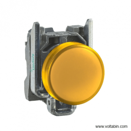
XB4BVM5
range of product
Easy Altivar 610
product or component type
Variable speed drive
product specific application
Fan, pump, compressor, conveyor
device short name
ATV610
variant
Standard version
product destination
Asynchronous motors
mounting mode
Cabinet mount
EMC filter
Integrated conforming to EN/IEC 61800-3 category C3 with 50 m
IP degree of protection
IP20
type of cooling
Forced convection
supply frequency
50…60 Hz +/-5 %
network number of phases
3 phases
[Us] rated supply voltage
380…460 V – 15…10 %
motor power kW
110 kW for normal duty
90 kW for heavy duty
motor power hp
150 hp for normal duty
125 hp for heavy duty
line current
201 A at 380 V (normal duty)
175.7 A at 460 V (normal duty)
170 A at 380 V (heavy duty)
149.1 A at 460 V (heavy duty)
prospective line Isc
50 kA
apparent power
140.0 kVA at 460 V (normal duty)
118.8 kVA at 460 V (heavy duty)
continuous output current
211 A at 2.5 kHz for normal duty
173 A at 2.5 kHz for heavy duty
maximum transient current
232 A during 60 s (normal duty)
260 A during 60 s (heavy duty)
asynchronous motor control profile
Variable torque standard
Optimized torque mode
Constant torque standard
output frequency
0.0001…0.5 kHz
nominal switching frequency
2.5 kHz
switching frequency
1…8 kHz adjustable
number of preset speeds
16 preset speeds
communication port protocol
Modbus serial
option card
Slot A: communication card, Profibus DP V1
Slot A: digital or analog I/O extension card
Slot A: relay output card
output voltage
<= power supply voltage
motor slip compensation
Can be suppressed
Adjustable
Not available in permanent magnet motor law
Automatic whatever the load
acceleration and deceleration ramps
Linear adjustable separately from 0.01 to 9000 s
S, U or customized
braking to standstill
By DC injection
protection type
Thermal protection: motor
Motor phase break: motor
Thermal protection: drive
Overheating: drive
Overcurrent between output phases and earth: drive
Overload of output voltage: drive
Short-circuit protection: drive
Motor phase break: drive
Overvoltages on the DC bus: drive
Line supply overvoltage: drive
Line supply undervoltage: drive
Line supply phase loss: drive
Overspeed: drive
Break on the control circuit: drive
frequency resolution
Display unit: 0.1 Hz
Analog input: 0.012/50 Hz
electrical connection
Control, screw terminal: 0.5…1.5 mm²
Line side, screw terminal: 2 x 50…3 x 120 mm²
Motor, screw terminal: 3 x 50…3 x 120 mm²
connector type
1 RJ45 (on the remote graphic terminal) for Modbus serial
physical interface
2-wire RS 485 for Modbus serial
transmission frame
RTU for Modbus serial
transmission rate
4.8, 9.6, 19.2, 38.4 kbit/s for Modbus serial
type of polarization
No impedance for Modbus serial
number of addresses
1…247 for Modbus serial
method of access
Slave
supply
External supply for digital inputs: 24 V DC (19…30 V), <1.25 mA, protection type: overload and short-circuit protection
Internal supply for reference potentiometer (1 to 10 kOhm): 10.5 V DC +/- 5 %, <10 mA, protection type: overload and short-circuit protection
local signalling
2 LEDs for local diagnostic
1 LED (yellow) for embedded communication status
2 LEDs (dual colour) for communication module status
1 LED (red) for presence of voltage
width
320 mm
height
852 mm
1159 mm with IP21 conformity kit
depth
390 mm
net weight
82 kg
analogue input number
3
analogue input type
AI1, AI2, AI3 software-configurable voltage: 0…10 V DC, impedance: 30 kOhm, resolution 12 bits
AI1, AI2, AI3 software-configurable current: 0…20 mA, impedance: 250 Ohm, resolution 12 bits
AI2, AI3 software-configurable temperature probe or water level sensor
discrete input number
6
discrete input type
DI1…DI6 programmable as logic input, 24 V DC (<= 30 V), impedance: 3.5 kOhm
DI5, DI6 programmable as pulse input: 0…30 kHz, 24 V DC (<= 30 V)
input compatibility
DI1…DI6: logic input level 1 PLC conforming to EN/IEC 61131-2
DI5, DI6: pulse input level 1 PLC conforming to IEC 65A-68
discrete input logic
Positive logic (source): DI1…DI6 configurable logic input, < 5 V (state 0), > 11 V (state 1)
Negative logic (sink): DI1…DI6 configurable logic input, > 16 V (state 0), < 10 V (state 1)
Positive logic (source): DI5, DI6 configurable pulse input, < 0.6 V (state 0), > 2.5 V (state 1)
analogue output number
2
analogue output type
Software-configurable current AQ1, AQ2: 0…20 mA, resolution 10 bits
Software-configurable voltage AQ1, AQ2: 0…10 V DC impedance 470 Ohm, resolution 10 bits
sampling duration
5 ms +/- 0.1 ms (AI1, AI2, AI3) – analog input
2 ms +/- 0.5 ms (DI1…DI6)configurable – discrete input
5 ms +/- 1 ms (DI5, DI6)configurable – pulse input
10 ms +/- 1 ms (AQ1, AQ2) – analog output
accuracy
+/- 0.6 % AI1, AI2, AI3 for a temperature variation 60 °C analog input
+/- 1 % AQ1, AQ2 for a temperature variation 60 °C analog output
linearity error
AI1, AI2, AI3: +/- 0.15 % of maximum value for analog input
AQ1, AQ2: +/- 0.2 % for analog output
relay output number
3
relay output type
Configurable relay logic R1: fault relay NO/NC electrical durability 100000 cycles
Configurable relay logic R2: sequence relay NO electrical durability 100000 cycles
Configurable relay logic R3: sequence relay NO electrical durability 100000 cycles
refresh time
Relay output (R1, R2, R3): 5 ms (+/- 0.5 ms)
minimum switching current
Relay output R1, R2, R3: 5 mA at 24 V DC
maximum switching current
Relay output R1, R2, R3 on resistive load, cos phi = 1: 3 A at 250 V AC
Relay output R1, R2, R3 on resistive load, cos phi = 1: 3 A at 30 V DC
Relay output R1, R2, R3 on inductive load, cos phi = 0.4 and L/R = 7 ms: 2 A at 250 V AC
Relay output R1, R2, R3 on inductive load, cos phi = 0.4 and L/R = 7 ms: 2 A at 30 V DC
isolation
Between power and control terminals
insulation resistance
> 1 MOhm 500 V DC for 1 minute to earth
noise level
76 dB conforming to 86/188/EEC
power dissipation in W
2026 W(forced convection) at 380 V, switching frequency 2.5 kHz
operating position
Vertical +/- 10 degree
electromagnetic compatibility
Electrostatic discharge immunity test level 3 conforming to IEC 61000-4-2
Radiated radio-frequency electromagnetic field immunity test level 3 conforming to IEC 61000-4-3
Electrical fast transient/burst immunity test level 4 conforming to IEC 61000-4-4
1.2/50 µs – 8/20 µs surge immunity test level 3 conforming to IEC 61000-4-5
Conducted radio-frequency immunity test level 3 conforming to IEC 61000-4-6
pollution degree
2 conforming to EN/IEC 61800-5-1
vibration resistance
1.5 mm peak to peak (f= 2…13 Hz) conforming to IEC 60068-2-6
1 gn (f= 13…200 Hz) conforming to IEC 60068-2-6
shock resistance
6 gn for 11 ms conforming to IEC 60068-2-27
relative humidity
5…95 % without condensation conforming to IEC 60068-2-3
ambient air temperature for operation
-15…45 °C (without derating)
45…60 °C (with derating factor)
operating altitude
<= 1000 m without derating
1000…4800 m with current derating 1 % per 100 m
environmental characteristic
Chemical pollution resistance class 3C3 conforming to EN/IEC 60721-3-3
Dust pollution resistance class 3S3 conforming to EN/IEC 60721-3-3
standards
EN/IEC 61800-3
Environment 2 category C3 EN/IEC 61800-3
EN/IEC 61800-5-1
IEC 60721-3
marking
CE
Unit Type of Package 1
PCE
Number of Units in Package 1
1
Package 1 Weight
96.344 kg
Package 1 Height
47 cm
Package 1 width
67 cm
Package 1 Length
103 cm
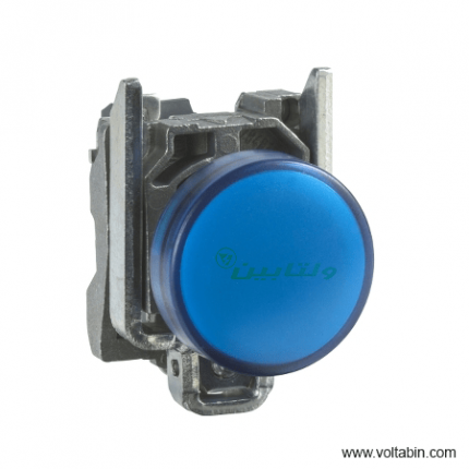
XB4BVM6
range of product
Easy Altivar 610
product or component type
Variable speed drive
product specific application
Fan, pump, compressor, conveyor
device short name
ATV610
variant
Standard version
product destination
Asynchronous motors
mounting mode
Cabinet mount
EMC filter
Integrated conforming to EN/IEC 61800-3 category C3 with 50 m
IP degree of protection
IP20
type of cooling
Forced convection
supply frequency
50…60 Hz +/-5 %
network number of phases
3 phases
[Us] rated supply voltage
380…460 V – 15…10 %
motor power kW
110 kW for normal duty
90 kW for heavy duty
motor power hp
150 hp for normal duty
125 hp for heavy duty
line current
201 A at 380 V (normal duty)
175.7 A at 460 V (normal duty)
170 A at 380 V (heavy duty)
149.1 A at 460 V (heavy duty)
prospective line Isc
50 kA
apparent power
140.0 kVA at 460 V (normal duty)
118.8 kVA at 460 V (heavy duty)
continuous output current
211 A at 2.5 kHz for normal duty
173 A at 2.5 kHz for heavy duty
maximum transient current
232 A during 60 s (normal duty)
260 A during 60 s (heavy duty)
asynchronous motor control profile
Variable torque standard
Optimized torque mode
Constant torque standard
output frequency
0.0001…0.5 kHz
nominal switching frequency
2.5 kHz
switching frequency
1…8 kHz adjustable
number of preset speeds
16 preset speeds
communication port protocol
Modbus serial
option card
Slot A: communication card, Profibus DP V1
Slot A: digital or analog I/O extension card
Slot A: relay output card
output voltage
<= power supply voltage
motor slip compensation
Can be suppressed
Adjustable
Not available in permanent magnet motor law
Automatic whatever the load
acceleration and deceleration ramps
Linear adjustable separately from 0.01 to 9000 s
S, U or customized
braking to standstill
By DC injection
protection type
Thermal protection: motor
Motor phase break: motor
Thermal protection: drive
Overheating: drive
Overcurrent between output phases and earth: drive
Overload of output voltage: drive
Short-circuit protection: drive
Motor phase break: drive
Overvoltages on the DC bus: drive
Line supply overvoltage: drive
Line supply undervoltage: drive
Line supply phase loss: drive
Overspeed: drive
Break on the control circuit: drive
frequency resolution
Display unit: 0.1 Hz
Analog input: 0.012/50 Hz
electrical connection
Control, screw terminal: 0.5…1.5 mm²
Line side, screw terminal: 2 x 50…3 x 120 mm²
Motor, screw terminal: 3 x 50…3 x 120 mm²
connector type
1 RJ45 (on the remote graphic terminal) for Modbus serial
physical interface
2-wire RS 485 for Modbus serial
transmission frame
RTU for Modbus serial
transmission rate
4.8, 9.6, 19.2, 38.4 kbit/s for Modbus serial
type of polarization
No impedance for Modbus serial
number of addresses
1…247 for Modbus serial
method of access
Slave
supply
External supply for digital inputs: 24 V DC (19…30 V), <1.25 mA, protection type: overload and short-circuit protection
Internal supply for reference potentiometer (1 to 10 kOhm): 10.5 V DC +/- 5 %, <10 mA, protection type: overload and short-circuit protection
local signalling
2 LEDs for local diagnostic
1 LED (yellow) for embedded communication status
2 LEDs (dual colour) for communication module status
1 LED (red) for presence of voltage
width
320 mm
height
852 mm
1159 mm with IP21 conformity kit
depth
390 mm
net weight
82 kg
analogue input number
3
analogue input type
AI1, AI2, AI3 software-configurable voltage: 0…10 V DC, impedance: 30 kOhm, resolution 12 bits
AI1, AI2, AI3 software-configurable current: 0…20 mA, impedance: 250 Ohm, resolution 12 bits
AI2, AI3 software-configurable temperature probe or water level sensor
discrete input number
6
discrete input type
DI1…DI6 programmable as logic input, 24 V DC (<= 30 V), impedance: 3.5 kOhm
DI5, DI6 programmable as pulse input: 0…30 kHz, 24 V DC (<= 30 V)
input compatibility
DI1…DI6: logic input level 1 PLC conforming to EN/IEC 61131-2
DI5, DI6: pulse input level 1 PLC conforming to IEC 65A-68
discrete input logic
Positive logic (source): DI1…DI6 configurable logic input, < 5 V (state 0), > 11 V (state 1)
Negative logic (sink): DI1…DI6 configurable logic input, > 16 V (state 0), < 10 V (state 1)
Positive logic (source): DI5, DI6 configurable pulse input, < 0.6 V (state 0), > 2.5 V (state 1)
analogue output number
2
analogue output type
Software-configurable current AQ1, AQ2: 0…20 mA, resolution 10 bits
Software-configurable voltage AQ1, AQ2: 0…10 V DC impedance 470 Ohm, resolution 10 bits
sampling duration
5 ms +/- 0.1 ms (AI1, AI2, AI3) – analog input
2 ms +/- 0.5 ms (DI1…DI6)configurable – discrete input
5 ms +/- 1 ms (DI5, DI6)configurable – pulse input
10 ms +/- 1 ms (AQ1, AQ2) – analog output
accuracy
+/- 0.6 % AI1, AI2, AI3 for a temperature variation 60 °C analog input
+/- 1 % AQ1, AQ2 for a temperature variation 60 °C analog output
linearity error
AI1, AI2, AI3: +/- 0.15 % of maximum value for analog input
AQ1, AQ2: +/- 0.2 % for analog output
relay output number
3
relay output type
Configurable relay logic R1: fault relay NO/NC electrical durability 100000 cycles
Configurable relay logic R2: sequence relay NO electrical durability 100000 cycles
Configurable relay logic R3: sequence relay NO electrical durability 100000 cycles
refresh time
Relay output (R1, R2, R3): 5 ms (+/- 0.5 ms)
minimum switching current
Relay output R1, R2, R3: 5 mA at 24 V DC
maximum switching current
Relay output R1, R2, R3 on resistive load, cos phi = 1: 3 A at 250 V AC
Relay output R1, R2, R3 on resistive load, cos phi = 1: 3 A at 30 V DC
Relay output R1, R2, R3 on inductive load, cos phi = 0.4 and L/R = 7 ms: 2 A at 250 V AC
Relay output R1, R2, R3 on inductive load, cos phi = 0.4 and L/R = 7 ms: 2 A at 30 V DC
isolation
Between power and control terminals
insulation resistance
> 1 MOhm 500 V DC for 1 minute to earth
noise level
76 dB conforming to 86/188/EEC
power dissipation in W
2026 W(forced convection) at 380 V, switching frequency 2.5 kHz
operating position
Vertical +/- 10 degree
electromagnetic compatibility
Electrostatic discharge immunity test level 3 conforming to IEC 61000-4-2
Radiated radio-frequency electromagnetic field immunity test level 3 conforming to IEC 61000-4-3
Electrical fast transient/burst immunity test level 4 conforming to IEC 61000-4-4
1.2/50 µs – 8/20 µs surge immunity test level 3 conforming to IEC 61000-4-5
Conducted radio-frequency immunity test level 3 conforming to IEC 61000-4-6
pollution degree
2 conforming to EN/IEC 61800-5-1
vibration resistance
1.5 mm peak to peak (f= 2…13 Hz) conforming to IEC 60068-2-6
1 gn (f= 13…200 Hz) conforming to IEC 60068-2-6
shock resistance
6 gn for 11 ms conforming to IEC 60068-2-27
relative humidity
5…95 % without condensation conforming to IEC 60068-2-3
ambient air temperature for operation
-15…45 °C (without derating)
45…60 °C (with derating factor)
operating altitude
<= 1000 m without derating
1000…4800 m with current derating 1 % per 100 m
environmental characteristic
Chemical pollution resistance class 3C3 conforming to EN/IEC 60721-3-3
Dust pollution resistance class 3S3 conforming to EN/IEC 60721-3-3
standards
EN/IEC 61800-3
Environment 2 category C3 EN/IEC 61800-3
EN/IEC 61800-5-1
IEC 60721-3
marking
CE
Unit Type of Package 1
PCE
Number of Units in Package 1
1
Package 1 Weight
96.344 kg
Package 1 Height
47 cm
Package 1 width
67 cm
Package 1 Length
103 cm
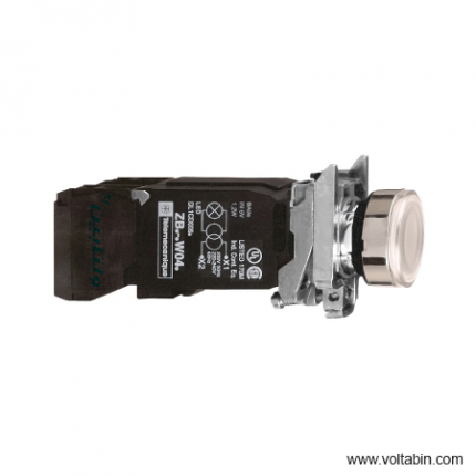
XB4BW3135
Range of Product Harmony XB4 Product or Component Type Illuminated push-button device short name XB4 Bezel material Chromium plated metal Fixing collar material Zamak Mounting diameter 0.87 in (22 mm) Sale per indivisible quantity 1 Head type Standard Shape of signaling unit head Round Type of operator Spring return Operator profile White flush Operator additional information With plain lens Contacts type and composition 1 NO + 1 NC Contact operation Slow-break Connections – terminals Screw clamp terminals, <= 2 x 1.5 mm² with cable end EN/IEC 60947-1
Screw clamp terminals, 1 x 0.22…2 x 2.5 mm² without cable end EN/IEC 60947-1Light source Incandescent Bulb base BA 9s Light block supply Via integral transformer 1.2 VA 6 V [Us] rated supply voltage 110…120 V AC 50/60 Hz Height 1.85 in (47 mm) Width 1.18 in (30 mm) Depth 3.98 in (101 mm) Terminals description ISO n°1 (21-22)NC
(13-14)NOProduct Weight 0.37 lb(US) (0.169 kg) Resistance to high pressure washer 1015.26 psi (7000000 Pa) 131 °F (55 °C) 0.1 m Contacts usage Standard contacts Positive opening With EN/IEC 60947-5-1 appendix K Operating travel 0.06 in (1.5 mm) NC changing electrical state)
0.10 in (2.6 mm) NO changing electrical state)
0.17 in (4.3 mm) total travel)Operating force 3.5 N NC changing electrical state
3.8 NMechanical durability 10000000 cycles Tightening torque 7.08…10.62 lbf.in (0.8…1.2 N.m) EN 60947-1 Shape of screw head Cross Philips no 1
Cross pozidriv No 1
Slotted flat Ø 4 mm
Slotted flat Ø 5.5 mmContacts material Silver alloy (Ag/Ni) Short-circuit protection 10 A cartridge fuse gG EN/IEC 60947-5-1 [Ith] conventional free air thermal current 10 A EN/IEC 60947-5-1 [Ui] rated insulation voltage 600 V 3)EN/IEC 60947-1 [Uimp] rated impulse withstand voltage 6 kV EN/IEC 60947-1 [Ie] rated operational current 3 A 240 V, AC-15, A600 EN/IEC 60947-5-1
6 A 120 V, AC-15, A600 EN/IEC 60947-5-1
0.1 A 600 V, DC-13, Q600 EN/IEC 60947-5-1
0.27 A 250 V, DC-13, Q600 EN/IEC 60947-5-1
0.55 A 125 V, DC-13, Q600 EN/IEC 60947-5-1
1.2 A 600 V, AC-15, A600 EN/IEC 60947-5-1Electrical durability 1000000 cycles, AC-15, 2 A 230 V 3600 cyc/h 0.5 EN/IEC 60947-5-1 appendix C
1000000 cycles, AC-15, 3 A 120 V 3600 cyc/h 0.5 EN/IEC 60947-5-1 appendix C
1000000 cycles, AC-15, 4 A 24 V 3600 cyc/h 0.5 EN/IEC 60947-5-1 appendix C
1000000 cycles, DC-13, 0.2 A 110 V 3600 cyc/h 0.5 EN/IEC 60947-5-1 appendix C
1000000 cycles, DC-13, 0.5 A 24 V 3600 cyc/h 0.5 EN/IEC 60947-5-1 appendix CElectrical reliability Λ < 10exp(-6) 5 V 1 mA in clean environment EN/IEC 60947-5-4
Λ < 10exp(-8) 17 V 5 mA in clean environment EN/IEC 60947-5-4Signalling type Steady Device presentation Complete product Protective treatment TH Ambient Air Temperature for Storage -40…158 °F (-40…70 °C) Ambient Air Temperature for Operation -40…131 °F (-40…55 °C) Electrical shock protection class Class I IEC 60536 IP degree of protection IP66 IEC 60529
IP67
IP69
IP69KNEMA degree of protection NEMA 13
NEMA 4XIK degree of protection IK06 IEC 50102 standards UL 508
EN/IEC 60947-1
JIS C8201-5-1
EN/IEC 60947-5-4
EN/IEC 60947-5-1
CSA C22.2 No 14
EN/IEC 60947-5-5
JIS C8201-1Product Certifications GL
CSA
LROS (Lloyds register of shipping)
DNV
UL Listed
BVVibration resistance 5 gn 2…500 Hz)IEC 60068-2-6 Shock resistance 30 gn 18 ms) half sine wave acceleration IEC 60068-2-27
50 gn 11 ms) half sine wave acceleration IEC 60068-2-27Unit Type of Package 1 PCE Number of Units in Package 1 1 Package 1 Height 5.04 in (12.8 cm) Package 1 Width 1.34 in (3.4 cm) Package 1 Length 1.89 in (4.8 cm) Package 1 Weight 5.96 oz (169.0 g)